Table of Contents
Advertisement
บริ ษ ั ท เอดี ด ี เฟอร์ เ นส จ ำกั ด
ADD FURNACE CO.,LTD.
44 ซอยบรมราชชนนี 70 ถนนบรมรำชชนนี แขวงศำลำธรรมสพน์ เขตทวี ว ั ฒ นำ กรุ ง เทพฯ 10170
โทร: 02-888-3472 โทร: ออกแบบ
https://www.add-furnace.com E-mail:
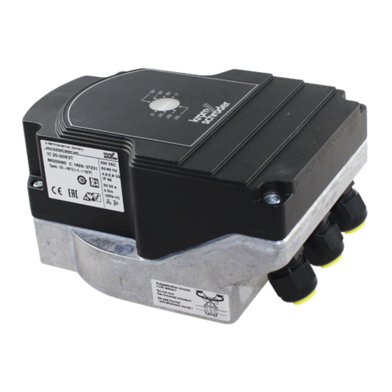
Actuators IC 20, IC 40
Technical Information · GB
3 Edition 04.14
• IC 20 for applications with continuous or three-point
step control and Automatic/Manual mode-
changeover for easy commissioning, IC 20..E with electronic
positioning function and adjustable behaviour in the event of cable
discontinuity
• IC 40 for complex applications with programmable functions for flexible
adjustment to the process, with statistics and fault history to support
service personnel
• A position indicator that can be read externally
• Spacious connection chamber for ease of installation
• Actuators can be delivered ready installed on butterfly valves BVG, BVGF,
BVA, BVAF, BVH, BVHS or linear flow control VFC
แฟกซ์ : 02-888-3258
08-08-170-170
:
sales@add-furnace.com
Advertisement
Table of Contents

Related Manuals for Krom Schroder IC 20


Summary of Contents for Krom Schroder IC 20
-
Page 1: Actuators Ic 20, Ic 40
Actuators IC 20, IC 40 Technical Information · GB 3 Edition 04.14 • IC 20 for applications with continuous or three-point step control and Automatic/Manual mode- changeover for easy commissioning, IC 20..E with electronic positioning function and adjustable behaviour in the event of cable discontinuity •... -
Page 2: Table Of Contents
4.5.9 2-point operation with switchover of the running times..35 1.1.1 IC 20, continuous control........7 4.5.10 3-point step operation with running time fractions. - Page 3 8 Accessories ......... . 74 8.1 IC 20, IC 40 Heat deflectors ....... 74 8.2 Adapter set for mounting an actuator IC 20, IC 40...
-
Page 4: Application
โทร: 02-888-3472 โทร: ออกแบบ แฟกซ์ : 02-888-3258 08-08-170-170 https://www.add-furnace.com E-mail: sales@add-furnace.com 1 Application IC 20 The actuators IC 20 and IC 40 are designed for all applications that require precise, controlled rotary movement between 0° and 90° . They can be mounted... - Page 5 บริ ษ ั ท เอดี ด ี เฟอร์ เ นส จ ำกั ด ADD FURNACE CO.,LTD. 44 ซอยบรมราชชนนี 70 ถนนบรมรำชชนนี แขวงศำลำธรรมสพน์ เขตทวี ว ั ฒ นำ กรุ ง เทพฯ 10170 โทร: 02-888-3472 โทร: ออกแบบ แฟกซ์ : 02-888-3258 08-08-170-170 https://www.add-furnace.com E-mail: sales@add-furnace.com Application Service technicians can call up statistical data using...
- Page 6 44 ซอยบรมราชชนนี 70 ถนนบรมรำชชนนี แขวงศำลำธรรมสพน์ เขตทวี ว ั ฒ นำ กรุ ง เทพฯ 10170 โทร: 02-888-3472 โทร: ออกแบบ แฟกซ์ : 02-888-3258 08-08-170-170 https://www.add-furnace.com E-mail: sales@add-furnace.com Application IC 20 with BVG 80 Roller hearth kiln in the ceramics industry Forging furnace...
-
Page 7: Examples Of Application
1.1.1 IC 20, continuous control For processes that require high temperature accuracy and low circulation in the furnace. The actuator IC 20 is controlled by a three-point step controller. 1.1.2 IC 20.E, continuous control For processes that require high temperature accuracy and low circulation in the furnace. -
Page 8: Ic 20, Modulating Control With Burner Control Unit Bcu 370
โทร: 02-888-3472 โทร: ออกแบบ แฟกซ์ : 02-888-3258 08-08-170-170 https://www.add-furnace.com E-mail: sales@add-furnace.com Application > Examples of application 1.1.3 IC 20, modulating control with burner control unit BCU 370 This connection option can be used modulating forced draught burners. The BCU 370 controls the fan and moves the butterfly valve to pre- purge and ignition position. -
Page 9: Ic 40, Staged Control
บริ ษ ั ท เอดี ด ี เฟอร์ เ นส จ ำกั ด ADD FURNACE CO.,LTD. 44 ซอยบรมราชชนนี 70 ถนนบรมรำชชนนี แขวงศำลำธรรมสพน์ เขตทวี ว ั ฒ นำ กรุ ง เทพฯ 10170 โทร: 02-888-3472 โทร: ออกแบบ แฟกซ์ : 02-888-3258 08-08-170-170 https://www.add-furnace.com E-mail: sales@add-furnace.com Application >... -
Page 10: Ic 40, Continuous Control By Three-Point Step Signal
บริ ษ ั ท เอดี ด ี เฟอร์ เ นส จ ำกั ด ADD FURNACE CO.,LTD. 44 ซอยบรมราชชนนี 70 ถนนบรมรำชชนนี แขวงศำลำธรรมสพน์ เขตทวี ว ั ฒ นำ กรุ ง เทพฯ 10170 โทร: 02-888-3472 โทร: ออกแบบ แฟกซ์ : 02-888-3258 08-08-170-170 https://www.add-furnace.com E-mail: sales@add-furnace.com Application >... -
Page 11: Ic 40, Staged Control With Pre-Purge
บริ ษ ั ท เอดี ด ี เฟอร์ เ นส จ ำกั ด ADD FURNACE CO.,LTD. 44 ซอยบรมราชชนนี 70 ถนนบรมรำชชนนี แขวงศำลำธรรมสพน์ เขตทวี ว ั ฒ นำ กรุ ง เทพฯ 10170 โทร: 02-888-3472 โทร: ออกแบบ แฟกซ์ : 02-888-3258 08-08-170-170 https://www.add-furnace.com E-mail: sales@add-furnace.com Application >... -
Page 12: Ic 40, Continuous Control With Defined Ignition Position
บริ ษ ั ท เอดี ด ี เฟอร์ เ นส จ ำกั ด ADD FURNACE CO.,LTD. 44 ซอยบรมราชชนนี 70 ถนนบรมรำชชนนี แขวงศำลำธรรมสพน์ เขตทวี ว ั ฒ นำ กรุ ง เทพฯ 10170 โทร: 02-888-3472 โทร: ออกแบบ แฟกซ์ : 02-888-3258 08-08-170-170 https://www.add-furnace.com E-mail: sales@add-furnace.com Application >... -
Page 13: Ic 40, Hot-Air Compensation
บริ ษ ั ท เอดี ด ี เฟอร์ เ นส จ ำกั ด ADD FURNACE CO.,LTD. 44 ซอยบรมราชชนนี 70 ถนนบรมรำชชนนี แขวงศำลำธรรมสพน์ เขตทวี ว ั ฒ นำ กรุ ง เทพฯ 10170 โทร: 02-888-3472 โทร: ออกแบบ แฟกซ์ : 02-888-3258 08-08-170-170 https://www.add-furnace.com E-mail: sales@add-furnace.com Application >... -
Page 14: Ic 40, Staged Control With Online Adjustment Of The Burner Capacity
บริ ษ ั ท เอดี ด ี เฟอร์ เ นส จ ำกั ด ADD FURNACE CO.,LTD. 44 ซอยบรมราชชนนี 70 ถนนบรมรำชชนนี แขวงศำลำธรรมสพน์ เขตทวี ว ั ฒ นำ กรุ ง เทพฯ 10170 โทร: 02-888-3472 โทร: ออกแบบ แฟกซ์ : 02-888-3258 08-08-170-170 https://www.add-furnace.com E-mail: sales@add-furnace.com Application >... -
Page 15: Certification
Approval for Russia Certified by Gosstandart pursuant to GOST R. Approved by Rostekhnadzor (RTN). Scan of the approval for Russia (RUS), see www.docuthek.com Kromschröder→Kromschröder, →Elster LBE→Products→03 Valves butterfly valves→Actuators IC 20, IC 40→Type of document: Certificate→IC B00069 (nationales Zertifikat Russland) (RUS) -
Page 16: Ic 20 Function
3 IC 20 function Automatic/Manual mode The actuator IC 20 moves towards 0° or 90° if it is energized Switchover between Automatic and Manual mode electrically at the related terminal. If the voltage is facilitates setting of the infinitely adjustable switching disconnected, the actuator stops at the current position. -
Page 17: Ic 20
44 ซอยบรมราชชนนี 70 ถนนบรมรำชชนนี แขวงศำลำธรรมสพน์ เขตทวี ว ั ฒ นำ กรุ ง เทพฯ 10170 โทร: 02-888-3472 โทร: ออกแบบ แฟกซ์ : 02-888-3258 08-08-170-170 https://www.add-furnace.com E-mail: sales@add-furnace.com IC 20 function 3.1 IC 20..T Connection diagram See page 70 (Project planning infor- mation). See page 76 (Technical data). -
Page 18: Ic 20
3.2.2 2-point step control Connect voltage to terminals 1 and 3. Set the DIP switch to 2-point step control, see page 20 (IC 20..E DIP switch). If an input signal is applied to terminal 5(OK), the actuator opens. If no input signal is applied to terminal 5, the ac- tuator closes. -
Page 19: Ic 20
44 ซอยบรมราชชนนี 70 ถนนบรมรำชชนนี แขวงศำลำธรรมสพน์ เขตทวี ว ั ฒ นำ กรุ ง เทพฯ 10170 โทร: 02-888-3472 โทร: ออกแบบ แฟกซ์ : 02-888-3258 08-08-170-170 https://www.add-furnace.com E-mail: sales@add-furnace.com IC 20 function 3 .3 IC 20..E Display 3.3.1 In Manual mode Blue LED Red LED Operating state Manual mode Flashing... -
Page 20: Ic 20
แฟกซ์ : 02-888-3258 08-08-170-170 https://www.add-furnace.com E-mail: sales@add-furnace.com IC 20 function 3 .4 IC 20..E DIP switch The setpoint device input, the load impedance of the current input, the behaviour in the event of cable discontinuity – 20 mA) or 2-point step control are set by means of a DIP switch on the actuator. -
Page 21: Ic 40 Function
Further visualization A detailed manual is available for the BCSoft software: ® and operation are performed on a PC using the http://www.docuthek.com Products 03 Valves and butterfly valves Kromschröder BCSoft software. ® Actuators IC 20, IC 40. -
Page 22: Operating Modes
บริ ษ ั ท เอดี ด ี เฟอร์ เ นส จ ำกั ด ADD FURNACE CO.,LTD. 44 ซอยบรมราชชนนี 70 ถนนบรมรำชชนนี แขวงศำลำธรรมสพน์ เขตทวี ว ั ฒ นำ กรุ ง เทพฯ 10170 โทร: 02-888-3472 โทร: ออกแบบ แฟกซ์ : 02-888-3258 08-08-170-170 https://www.add-furnace.com E-mail: sales@add-furnace.com IC 40 function 4.1 Operating modes... -
Page 23: Running Times
บริ ษ ั ท เอดี ด ี เฟอร์ เ นส จ ำกั ด ADD FURNACE CO.,LTD. 44 ซอยบรมราชชนนี 70 ถนนบรมรำชชนนี แขวงศำลำธรรมสพน์ เขตทวี ว ั ฒ นำ กรุ ง เทพฯ 10170 โทร: 02-888-3472 โทร: ออกแบบ แฟกซ์ : 02-888-3258 08-08-170-170 https://www.add-furnace.com E-mail: sales@add-furnace.com IC 40 function 4..4 Running times... -
Page 24: Standard Operating Modes 1 - 12
บริ ษ ั ท เอดี ด ี เฟอร์ เ นส จ ำกั ด ADD FURNACE CO.,LTD. 44 ซอยบรมราชชนนี 70 ถนนบรมรำชชนนี แขวงศำลำธรรมสพน์ เขตทวี ว ั ฒ นำ กรุ ง เทพฯ 10170 โทร: 02-888-3472 โทร: ออกแบบ แฟกซ์ : 02-888-3258 08-08-170-170 https://www.add-furnace.com E-mail: sales@add-furnace.com IC 40 function 4.5 Standard operating modes 1 –... -
Page 25: 2-Point Operation With Flame Proving Period
บริ ษ ั ท เอดี ด ี เฟอร์ เ นส จ ำกั ด ADD FURNACE CO.,LTD. 44 ซอยบรมราชชนนี 70 ถนนบรมรำชชนนี แขวงศำลำธรรมสพน์ เขตทวี ว ั ฒ นำ กรุ ง เทพฯ 10170 โทร: 02-888-3472 โทร: ออกแบบ แฟกซ์ : 02-888-3258 08-08-170-170 https://www.add-furnace.com E-mail: sales@add-furnace.com IC 40 function 4.5.2 2-point operation with flame proving period... -
Page 26: 2-Step Operation With One Or Two Digital Inputs
บริ ษ ั ท เอดี ด ี เฟอร์ เ นส จ ำกั ด ADD FURNACE CO.,LTD. 44 ซอยบรมราชชนนี 70 ถนนบรมรำชชนนี แขวงศำลำธรรมสพน์ เขตทวี ว ั ฒ นำ กรุ ง เทพฯ 10170 โทร: 02-888-3472 โทร: ออกแบบ แฟกซ์ : 02-888-3258 08-08-170-170 https://www.add-furnace.com E-mail: sales@add-furnace.com IC 40 function >... - Page 27 บริ ษ ั ท เอดี ด ี เฟอร์ เ นส จ ำกั ด ADD FURNACE CO.,LTD. 44 ซอยบรมราชชนนี 70 ถนนบรมรำชชนนี แขวงศำลำธรรมสพน์ เขตทวี ว ั ฒ นำ กรุ ง เทพฯ 10170 โทร: 02-888-3472 โทร: ออกแบบ แฟกซ์ : 02-888-3258 08-08-170-170 https://www.add-furnace.com E-mail: sales@add-furnace.com IC 40 function >...
-
Page 28: 2-Step Operation With Two Digital Inputs
บริ ษ ั ท เอดี ด ี เฟอร์ เ นส จ ำกั ด ADD FURNACE CO.,LTD. 44 ซอยบรมราชชนนี 70 ถนนบรมรำชชนนี แขวงศำลำธรรมสพน์ เขตทวี ว ั ฒ นำ กรุ ง เทพฯ 10170 โทร: 02-888-3472 โทร: ออกแบบ แฟกซ์ : 02-888-3258 08-08-170-170 https://www.add-furnace.com E-mail: sales@add-furnace.com IC 40 function >... -
Page 29: 3-Point Step Operation
บริ ษ ั ท เอดี ด ี เฟอร์ เ นส จ ำกั ด ADD FURNACE CO.,LTD. 44 ซอยบรมราชชนนี 70 ถนนบรมรำชชนนี แขวงศำลำธรรมสพน์ เขตทวี ว ั ฒ นำ กรุ ง เทพฯ 10170 โทร: 02-888-3472 โทร: ออกแบบ แฟกซ์ : 02-888-3258 08-08-170-170 https://www.add-furnace.com E-mail: sales@add-furnace.com IC 40 function >... -
Page 30: 3-Step Operation With One Or Two Digital Inputs
บริ ษ ั ท เอดี ด ี เฟอร์ เ นส จ ำกั ด ADD FURNACE CO.,LTD. 44 ซอยบรมราชชนนี 70 ถนนบรมรำชชนนี แขวงศำลำธรรมสพน์ เขตทวี ว ั ฒ นำ กรุ ง เทพฯ 10170 โทร: 02-888-3472 โทร: ออกแบบ แฟกซ์ : 02-888-3258 08-08-170-170 https://www.add-furnace.com E-mail: sales@add-furnace.com IC 40 function >... - Page 31 บริ ษ ั ท เอดี ด ี เฟอร์ เ นส จ ำกั ด ADD FURNACE CO.,LTD. 44 ซอยบรมราชชนนี 70 ถนนบรมรำชชนนี แขวงศำลำธรรมสพน์ เขตทวี ว ั ฒ นำ กรุ ง เทพฯ 10170 โทร: 02-888-3472 โทร: ออกแบบ แฟกซ์ : 02-888-3258 08-08-170-170 https://www.add-furnace.com E-mail: sales@add-furnace.com IC 40 function >...
-
Page 32: 2-Point Operation With Switchover Of The Adjustment Angle For The "Open" Position
บริ ษ ั ท เอดี ด ี เฟอร์ เ นส จ ำกั ด ADD FURNACE CO.,LTD. 44 ซอยบรมราชชนนี 70 ถนนบรมรำชชนนี แขวงศำลำธรรมสพน์ เขตทวี ว ั ฒ นำ กรุ ง เทพฯ 10170 โทร: 02-888-3472 โทร: ออกแบบ แฟกซ์ : 02-888-3258 08-08-170-170 https://www.add-furnace.com E-mail: sales@add-furnace.com IC 40 function >... - Page 33 บริ ษ ั ท เอดี ด ี เฟอร์ เ นส จ ำกั ด ADD FURNACE CO.,LTD. 44 ซอยบรมราชชนนี 70 ถนนบรมรำชชนนี แขวงศำลำธรรมสพน์ เขตทวี ว ั ฒ นำ กรุ ง เทพฯ 10170 โทร: 02-888-3472 โทร: ออกแบบ แฟกซ์ : 02-888-3258 08-08-170-170 https://www.add-furnace.com E-mail: sales@add-furnace.com IC 40 function >...
-
Page 34: 2-Point Operation With Input-Dependent Adjustment Angle For The "Open" Position
บริ ษ ั ท เอดี ด ี เฟอร์ เ นส จ ำกั ด ADD FURNACE CO.,LTD. 44 ซอยบรมราชชนนี 70 ถนนบรมรำชชนนี แขวงศำลำธรรมสพน์ เขตทวี ว ั ฒ นำ กรุ ง เทพฯ 10170 โทร: 02-888-3472 โทร: ออกแบบ แฟกซ์ : 02-888-3258 08-08-170-170 https://www.add-furnace.com E-mail: sales@add-furnace.com IC 40 function >... -
Page 35: 2-Point Operation With Switchover Of The Running Times
บริ ษ ั ท เอดี ด ี เฟอร์ เ นส จ ำกั ด ADD FURNACE CO.,LTD. 44 ซอยบรมราชชนนี 70 ถนนบรมรำชชนนี แขวงศำลำธรรมสพน์ เขตทวี ว ั ฒ นำ กรุ ง เทพฯ 10170 โทร: 02-888-3472 โทร: ออกแบบ แฟกซ์ : 02-888-3258 08-08-170-170 https://www.add-furnace.com E-mail: sales@add-furnace.com IC 40 function >... -
Page 36: 3-Point Step Operation With Running Time Fractions
บริ ษ ั ท เอดี ด ี เฟอร์ เ นส จ ำกั ด ADD FURNACE CO.,LTD. 44 ซอยบรมราชชนนี 70 ถนนบรมรำชชนนี แขวงศำลำธรรมสพน์ เขตทวี ว ั ฒ นำ กรุ ง เทพฯ 10170 โทร: 02-888-3472 โทร: ออกแบบ แฟกซ์ : 02-888-3258 08-08-170-170 https://www.add-furnace.com E-mail: sales@add-furnace.com IC 40 function >... - Page 37 บริ ษ ั ท เอดี ด ี เฟอร์ เ นส จ ำกั ด ADD FURNACE CO.,LTD. 44 ซอยบรมราชชนนี 70 ถนนบรมรำชชนนี แขวงศำลำธรรมสพน์ เขตทวี ว ั ฒ นำ กรุ ง เทพฯ 10170 โทร: 02-888-3472 โทร: ออกแบบ แฟกซ์ : 02-888-3258 08-08-170-170 https://www.add-furnace.com E-mail: sales@add-furnace.com IC 40 function >...
-
Page 38: 3-Step Operation With Two Digital Inputs
บริ ษ ั ท เอดี ด ี เฟอร์ เ นส จ ำกั ด ADD FURNACE CO.,LTD. 44 ซอยบรมราชชนนี 70 ถนนบรมรำชชนนี แขวงศำลำธรรมสพน์ เขตทวี ว ั ฒ นำ กรุ ง เทพฯ 10170 โทร: 02-888-3472 โทร: ออกแบบ แฟกซ์ : 02-888-3258 08-08-170-170 https://www.add-furnace.com E-mail: sales@add-furnace.com IC 40 function >... -
Page 39: 3-Point Step Operation With Low Position
บริ ษ ั ท เอดี ด ี เฟอร์ เ นส จ ำกั ด ADD FURNACE CO.,LTD. 44 ซอยบรมราชชนนี 70 ถนนบรมรำชชนนี แขวงศำลำธรรมสพน์ เขตทวี ว ั ฒ นำ กรุ ง เทพฯ 10170 โทร: 02-888-3472 โทร: ออกแบบ แฟกซ์ : 02-888-3258 08-08-170-170 https://www.add-furnace.com E-mail: sales@add-furnace.com IC 40 function >... -
Page 40: Analogue Operating Modes 21 - 27
บริ ษ ั ท เอดี ด ี เฟอร์ เ นส จ ำกั ด ADD FURNACE CO.,LTD. 44 ซอยบรมราชชนนี 70 ถนนบรมรำชชนนี แขวงศำลำธรรมสพน์ เขตทวี ว ั ฒ นำ กรุ ง เทพฯ 10170 โทร: 02-888-3472 โทร: ออกแบบ แฟกซ์ : 02-888-3258 08-08-170-170 https://www.add-furnace.com E-mail: sales@add-furnace.com The adjustment angle for the “open”... - Page 41 บริ ษ ั ท เอดี ด ี เฟอร์ เ นส จ ำกั ด ADD FURNACE CO.,LTD. 44 ซอยบรมราชชนนี 70 ถนนบรมรำชชนนี แขวงศำลำธรรมสพน์ เขตทวี ว ั ฒ นำ กรุ ง เทพฯ 10170 โทร: 02-888-3472 โทร: ออกแบบ แฟกซ์ : 02-888-3258 08-08-170-170 https://www.add-furnace.com E-mail: sales@add-furnace.com IC 40 function >...
-
Page 42: 2-Point Operation With Switchover Of The Adjustment Angle For The "Open" Position
บริ ษ ั ท เอดี ด ี เฟอร์ เ นส จ ำกั ด ADD FURNACE CO.,LTD. 44 ซอยบรมราชชนนี 70 ถนนบรมรำชชนนี แขวงศำลำธรรมสพน์ เขตทวี ว ั ฒ นำ กรุ ง เทพฯ 10170 โทร: 02-888-3472 โทร: ออกแบบ แฟกซ์ : 02-888-3258 08-08-170-170 https://www.add-furnace.com E-mail: sales@add-furnace.com IC 40 function >... - Page 43 บริ ษ ั ท เอดี ด ี เฟอร์ เ นส จ ำกั ด ADD FURNACE CO.,LTD. 44 ซอยบรมราชชนนี 70 ถนนบรมรำชชนนี แขวงศำลำธรรมสพน์ เขตทวี ว ั ฒ นำ กรุ ง เทพฯ 10170 โทร: 02-888-3472 โทร: ออกแบบ แฟกซ์ : 02-888-3258 08-08-170-170 https://www.add-furnace.com E-mail: sales@add-furnace.com IC 40 function >...
-
Page 44: 2-Point Operation With Input-Dependent Adjustment Angle For The "Open" Position
บริ ษ ั ท เอดี ด ี เฟอร์ เ นส จ ำกั ด ADD FURNACE CO.,LTD. 44 ซอยบรมราชชนนี 70 ถนนบรมรำชชนนี แขวงศำลำธรรมสพน์ เขตทวี ว ั ฒ นำ กรุ ง เทพฯ 10170 โทร: 02-888-3472 โทร: ออกแบบ แฟกซ์ : 02-888-3258 08-08-170-170 https://www.add-furnace.com E-mail: sales@add-furnace.com IC 40 function >... -
Page 45: 2-Point Operation With Switchover Of The Running Times
บริ ษ ั ท เอดี ด ี เฟอร์ เ นส จ ำกั ด ADD FURNACE CO.,LTD. 44 ซอยบรมราชชนนี 70 ถนนบรมรำชชนนี แขวงศำลำธรรมสพน์ เขตทวี ว ั ฒ นำ กรุ ง เทพฯ 10170 โทร: 02-888-3472 โทร: ออกแบบ แฟกซ์ : 02-888-3258 08-08-170-170 https://www.add-furnace.com E-mail: sales@add-furnace.com IC 40 function >... - Page 46 บริ ษ ั ท เอดี ด ี เฟอร์ เ นส จ ำกั ด ADD FURNACE CO.,LTD. 44 ซอยบรมราชชนนี 70 ถนนบรมรำชชนนี แขวงศำลำธรรมสพน์ เขตทวี ว ั ฒ นำ กรุ ง เทพฯ 10170 โทร: 02-888-3472 โทร: ออกแบบ แฟกซ์ : 02-888-3258 08-08-170-170 https://www.add-furnace.com E-mail: sales@add-furnace.com IC 40 function >...
-
Page 47: 2-Point Operation With Characteristic Curve Switchover I
บริ ษ ั ท เอดี ด ี เฟอร์ เ นส จ ำกั ด ADD FURNACE CO.,LTD. 44 ซอยบรมราชชนนี 70 ถนนบรมรำชชนนี แขวงศำลำธรรมสพน์ เขตทวี ว ั ฒ นำ กรุ ง เทพฯ 10170 โทร: 02-888-3472 โทร: ออกแบบ แฟกซ์ : 02-888-3258 08-08-170-170 https://www.add-furnace.com E-mail: sales@add-furnace.com IC 40 function >... - Page 48 บริ ษ ั ท เอดี ด ี เฟอร์ เ นส จ ำกั ด ADD FURNACE CO.,LTD. 44 ซอยบรมราชชนนี 70 ถนนบรมรำชชนนี แขวงศำลำธรรมสพน์ เขตทวี ว ั ฒ นำ กรุ ง เทพฯ 10170 โทร: 02-888-3472 โทร: ออกแบบ แฟกซ์ : 02-888-3258 08-08-170-170 https://www.add-furnace.com E-mail: sales@add-furnace.com IC 40 function >...
-
Page 49: 2-Point Operation With Characteristic Curve Switchover Ii
บริ ษ ั ท เอดี ด ี เฟอร์ เ นส จ ำกั ด ADD FURNACE CO.,LTD. 44 ซอยบรมราชชนนี 70 ถนนบรมรำชชนนี แขวงศำลำธรรมสพน์ เขตทวี ว ั ฒ นำ กรุ ง เทพฯ 10170 โทร: 02-888-3472 โทร: ออกแบบ แฟกซ์ : 02-888-3258 08-08-170-170 https://www.add-furnace.com E-mail: sales@add-furnace.com IC 40 function >... - Page 50 บริ ษ ั ท เอดี ด ี เฟอร์ เ นส จ ำกั ด ADD FURNACE CO.,LTD. 44 ซอยบรมราชชนนี 70 ถนนบรมรำชชนนี แขวงศำลำธรรมสพน์ เขตทวี ว ั ฒ นำ กรุ ง เทพฯ 10170 โทร: 02-888-3472 โทร: ออกแบบ แฟกซ์ : 02-888-3258 08-08-170-170 https://www.add-furnace.com E-mail: sales@add-furnace.com IC 40 function >...
-
Page 51: 2-Step Operation With Two Digital Inputs And Variable
บริ ษ ั ท เอดี ด ี เฟอร์ เ นส จ ำกั ด ADD FURNACE CO.,LTD. 44 ซอยบรมราชชนนี 70 ถนนบรมรำชชนนี แขวงศำลำธรรมสพน์ เขตทวี ว ั ฒ นำ กรุ ง เทพฯ 10170 โทร: 02-888-3472 โทร: ออกแบบ แฟกซ์ : 02-888-3258 08-08-170-170 https://www.add-furnace.com E-mail: sales@add-furnace.com IC 40 function >... -
Page 52: Safety Closing Function
บริ ษ ั ท เอดี ด ี เฟอร์ เ นส จ ำกั ด ADD FURNACE CO.,LTD. 44 ซอยบรมราชชนนี 70 ถนนบรมรำชชนนี แขวงศำลำธรรมสพน์ เขตทวี ว ั ฒ นำ กรุ ง เทพฯ 10170 โทร: 02-888-3472 โทร: ออกแบบ แฟกซ์ : 02-888-3258 08-08-170-170 https://www.add-furnace.com E-mail: sales@add-furnace.com IC 40 function >... -
Page 53: Parameters
บริ ษ ั ท เอดี ด ี เฟอร์ เ นส จ ำกั ด ADD FURNACE CO.,LTD. 44 ซอยบรมราชชนนี 70 ถนนบรมรำชชนนี แขวงศำลำธรรมสพน์ เขตทวี ว ั ฒ นำ กรุ ง เทพฯ 10170 โทร: 02-888-3472 โทร: ออกแบบ แฟกซ์ : 02-888-3258 08-08-170-170 https://www.add-furnace.com E-mail: sales@add-furnace.com IC 40 function 4 .7 Parameters... -
Page 54: Parameter Sets
บริ ษ ั ท เอดี ด ี เฟอร์ เ นส จ ำกั ด ADD FURNACE CO.,LTD. 44 ซอยบรมราชชนนี 70 ถนนบรมรำชชนนี แขวงศำลำธรรมสพน์ เขตทวี ว ั ฒ นำ กรุ ง เทพฯ 10170 โทร: 02-888-3472 โทร: ออกแบบ แฟกซ์ : 02-888-3258 08-08-170-170 https://www.add-furnace.com E-mail: sales@add-furnace.com IC 40 function >... - Page 55 บริ ษ ั ท เอดี ด ี เฟอร์ เ นส จ ำกั ด ADD FURNACE CO.,LTD. 44 ซอยบรมราชชนนี 70 ถนนบรมรำชชนนี แขวงศำลำธรรมสพน์ เขตทวี ว ั ฒ นำ กรุ ง เทพฯ 10170 โทร: 02-888-3472 โทร: ออกแบบ แฟกซ์ : 02-888-3258 08-08-170-170 https://www.add-furnace.com E-mail: sales@add-furnace.com IC 40 function >...
-
Page 56: Factory Default Parameters
บริ ษ ั ท เอดี ด ี เฟอร์ เ นส จ ำกั ด ADD FURNACE CO.,LTD. 44 ซอยบรมราชชนนี 70 ถนนบรมรำชชนนี แขวงศำลำธรรมสพน์ เขตทวี ว ั ฒ นำ กรุ ง เทพฯ 10170 โทร: 02-888-3472 โทร: ออกแบบ แฟกซ์ : 02-888-3258 08-08-170-170 https://www.add-furnace.com E-mail: sales@add-furnace.com IC 40 function >... -
Page 57: Inputs
บริ ษ ั ท เอดี ด ี เฟอร์ เ นส จ ำกั ด ADD FURNACE CO.,LTD. 44 ซอยบรมราชชนนี 70 ถนนบรมรำชชนนี แขวงศำลำธรรมสพน์ เขตทวี ว ั ฒ นำ กรุ ง เทพฯ 10170 โทร: 02-888-3472 โทร: ออกแบบ แฟกซ์ : 02-888-3258 08-08-170-170 https://www.add-furnace.com E-mail: sales@add-furnace.com IC 40 function 4 .8 Inputs... - Page 58 บริ ษ ั ท เอดี ด ี เฟอร์ เ นส จ ำกั ด ADD FURNACE CO.,LTD. 44 ซอยบรมราชชนนี 70 ถนนบรมรำชชนนี แขวงศำลำธรรมสพน์ เขตทวี ว ั ฒ นำ กรุ ง เทพฯ 10170 โทร: 02-888-3472 โทร: ออกแบบ แฟกซ์ : 02-888-3258 08-08-170-170 https://www.add-furnace.com E-mail: sales@add-furnace.com IC 40 function >...
-
Page 59: Outputs
บริ ษ ั ท เอดี ด ี เฟอร์ เ นส จ ำกั ด ADD FURNACE CO.,LTD. 44 ซอยบรมราชชนนี 70 ถนนบรมรำชชนนี แขวงศำลำธรรมสพน์ เขตทวี ว ั ฒ นำ กรุ ง เทพฯ 10170 โทร: 02-888-3472 โทร: ออกแบบ แฟกซ์ : 02-888-3258 08-08-170-170 https://www.add-furnace.com E-mail: sales@add-furnace.com IC 40 function 4.9 Outputs... -
Page 60: Manual Mode
บริ ษ ั ท เอดี ด ี เฟอร์ เ นส จ ำกั ด ADD FURNACE CO.,LTD. 44 ซอยบรมราชชนนี 70 ถนนบรมรำชชนนี แขวงศำลำธรรมสพน์ เขตทวี ว ั ฒ นำ กรุ ง เทพฯ 10170 โทร: 02-888-3472 โทร: ออกแบบ แฟกซ์ : 02-888-3258 08-08-170-170 https://www.add-furnace.com E-mail: sales@add-furnace.com IC 40 function 4 .10 Manual mode... -
Page 61: Statistics
บริ ษ ั ท เอดี ด ี เฟอร์ เ นส จ ำกั ด ADD FURNACE CO.,LTD. 44 ซอยบรมราชชนนี 70 ถนนบรมรำชชนนี แขวงศำลำธรรมสพน์ เขตทวี ว ั ฒ นำ กรุ ง เทพฯ 10170 โทร: 02-888-3472 โทร: ออกแบบ แฟกซ์ : 02-888-3258 08-08-170-170 https://www.add-furnace.com E-mail: sales@add-furnace.com IC 40 function 4.11 Statistics... -
Page 62: Ic 40 Connection Diagram
บริ ษ ั ท เอดี ด ี เฟอร์ เ นส จ ำกั ด ADD FURNACE CO.,LTD. 44 ซอยบรมราชชนนี 70 ถนนบรมรำชชนนี แขวงศำลำธรรมสพน์ เขตทวี ว ั ฒ นำ กรุ ง เทพฯ 10170 โทร: 02-888-3472 โทร: ออกแบบ แฟกซ์ : 02-888-3258 08-08-170-170 https://www.add-furnace.com E-mail: sales@add-furnace.com IC 40 function 4.12 IC 40 connection diagram... -
Page 63: Display
บริ ษ ั ท เอดี ด ี เฟอร์ เ นส จ ำกั ด ADD FURNACE CO.,LTD. 44 ซอยบรมราชชนนี 70 ถนนบรมรำชชนนี แขวงศำลำธรรมสพน์ เขตทวี ว ั ฒ นำ กรุ ง เทพฯ 10170 โทร: 02-888-3472 โทร: ออกแบบ แฟกซ์ : 02-888-3258 08-08-170-170 https://www.add-furnace.com E-mail: sales@add-furnace.com IC 40 function 4 .13 Display... - Page 64 บริ ษ ั ท เอดี ด ี เฟอร์ เ นส จ ำกั ด ADD FURNACE CO.,LTD. 44 ซอยบรมราชชนนี 70 ถนนบรมรำชชนนี แขวงศำลำธรรมสพน์ เขตทวี ว ั ฒ นำ กรุ ง เทพฯ 10170 โทร: 02-888-3472 โทร: ออกแบบ แฟกซ์ : 02-888-3258 08-08-170-170 https://www.add-furnace.com E-mail: sales@add-furnace.com IC 40 function >...
-
Page 65: Relay Outputs Ro 1 And Ro 2 Function
บริ ษ ั ท เอดี ด ี เฟอร์ เ นส จ ำกั ด ADD FURNACE CO.,LTD. 44 ซอยบรมราชชนนี 70 ถนนบรมรำชชนนี แขวงศำลำธรรมสพน์ เขตทวี ว ั ฒ นำ กรุ ง เทพฯ 10170 โทร: 02-888-3472 โทร: ออกแบบ แฟกซ์ : 02-888-3258 08-08-170-170 https://www.add-furnace.com E-mail: sales@add-furnace.com IC 40 function 4.14 Relay outputs RO 1 and RO 2 function... -
Page 66: Replacement Possibilities For Actuators
โทร: 02-888-3472 โทร: ออกแบบ แฟกซ์ : 02-888-3258 08-08-170-170 https://www.add-furnace.com E-mail: sales@add-furnace.com 5 Replacement possibilities for actuators 5.1 GT 31 is to be replaced with IC 20 GT 31 Actuator Actuator IC 20 Running time [s/90° ] Running time [s/90° ] Mains voltage: 24 V AC Mains voltage: –... -
Page 67: Gt 31 Is To Be Replaced With Ic 40
บริ ษ ั ท เอดี ด ี เฟอร์ เ นส จ ำกั ด ADD FURNACE CO.,LTD. 44 ซอยบรมราชชนนี 70 ถนนบรมรำชชนนี แขวงศำลำธรรมสพน์ เขตทวี ว ั ฒ นำ กรุ ง เทพฯ 10170 โทร: 02-888-3472 โทร: ออกแบบ แฟกซ์ : 02-888-3258 08-08-170-170 https://www.add-furnace.com E-mail: sales@add-furnace.com Replacement possibilities for actuators 5.2 GT 31 is to be replaced with IC 40... -
Page 68: M5/M6 Is To Be Replaced With Ic 40
บริ ษ ั ท เอดี ด ี เฟอร์ เ นส จ ำกั ด ADD FURNACE CO.,LTD. 44 ซอยบรมราชชนนี 70 ถนนบรมรำชชนนี แขวงศำลำธรรมสพน์ เขตทวี ว ั ฒ นำ กรุ ง เทพฯ 10170 โทร: 02-888-3472 โทร: ออกแบบ แฟกซ์ : 02-888-3258 08-08-170-170 https://www.add-furnace.com E-mail: sales@add-furnace.com Replacement possibilities for actuators 5.3 M5/M6 is to be replaced with IC 40... -
Page 69: Selection
230 V AC, -15/+10% this specification is omitted. 120 V AC, -15/+10% 100 – 230 V AC, ± 10% 3) IC 20-07: 2.5 Nm, IC 20-15/-30/-60: 3.0 Nm, IC 40: 2.5 Torque: Nm, IC 40..S: 3.0 Nm. 2.5 Nm 3 Nm 4) If “none”, this specification is omitted. -
Page 70: Project Planning Information
Load resistors may not be fitted inside the IC 40 for Observe EMC Directive for installation of signal lines. reasons 7.1.2 IC 20 relating to heat dissipation. When operating two or more actuators in parallel, they Example for 24 V DC and 10 mA: must Load resistor = 3.3 kΩ, 0.6 W. - Page 71 บริ ษ ั ท เอดี ด ี เฟอร์ เ นส จ ำกั ด ADD FURNACE CO.,LTD. 44 ซอยบรมราชชนนี 70 ถนนบรมรำชชนนี แขวงศำลำธรรมสพน์ เขตทวี ว ั ฒ นำ กรุ ง เทพฯ 10170 โทร: 02-888-3472 โทร: ออกแบบ แฟกซ์ : 02-888-3258 08-08-170-170 https://www.add-furnace.com E-mail: sales@add-furnace.com Project planning information >...
-
Page 72: Feedback Potentiometer
The feedback potentiometer can be retrofitted on actuator IC 20, see page 74 (Accessories).On the IC 20..E, a 4 – 20 mA continuous signal is used for position feedback. IC 40 cannot be retrofitted with a potentiometer. As an... -
Page 73: Installation
E-mail: sales@add-furnace.com Project planning information 7 .3 Installation Installation position of actuators IC 20, IC 40: vertical or horizontal, not upside down. If the actuator is used with hot air, the pipeline 7 .4 IC 40 commissioning should be adequately insulated so as to reduce When mains power is connected, the actuator IC the ambient temperature. -
Page 74: Accessories
โทร: 02-888-3472 โทร: ออกแบบ แฟกซ์ : 02-888-3258 08-08-170-170 https://www.add-furnace.com E-mail: sales@add-furnace.com 8 .2 Adapter set for mounting an actuator IC 20, IC 8 Accessories 40 onto a butterfly valve DKL, DKG 8.1 IC 20, IC 40 Heat deflectors Order number: 74921672 In conjunction with butterfly valves BVH, BVHS for hot air, 8 .3 IC 20, IC 40 “single application”... -
Page 75: Ic 20 Potentiometer Installation Set
44 ซอยบรมราชชนนี 70 ถนนบรมรำชชนนี แขวงศำลำธรรมสพน์ เขตทวี ว ั ฒ นำ กรุ ง เทพฯ 10170 โทร: 02-888-3472 โทร: ออกแบบ แฟกซ์ : 02-888-3258 08-08-170-170 https://www.add-furnace.com E-mail: sales@add-furnace.com Accessories 8.4 IC 20 potentiometer installation set 8.5.1 Opto-adapter PCO 200 1000 Ω feedback potentiometer. BCSoft CD-ROM included, ® The power consumption of the potentiometer is max. 0.5 Order No.: 74960625. -
Page 76: Technical Data
08-08-170-170 https://www.add-furnace.com E-mail: sales@add-furnace.com 9 Technical data 9.1.1 IC 20 Power consumption: 9.1 IC 20, IC 20..E 4.9 VA at 50 Hz, 5.8 VA at 60 Hz. Mains voltage: 9.1.2 IC 20..E 120 V AC, -15/+10%, 50/60 Hz, Power consumption: 230 V AC, -15/+10%, 50/60 Hz. -
Page 77: Ic 40
บริ ษ ั ท เอดี ด ี เฟอร์ เ นส จ ำกั ด ADD FURNACE CO.,LTD. 44 ซอยบรมราชชนนี 70 ถนนบรมรำชชนนี แขวงศำลำธรรมสพน์ เขตทวี ว ั ฒ นำ กรุ ง เทพฯ 10170 โทร: 02-888-3472 โทร: ออกแบบ แฟกซ์ : 02-888-3258 08-08-170-170 https://www.add-furnace.com E-mail: sales@add-furnace.com Technical data 9.2 IC 40... -
Page 78: Running Times And Torques
E-mail: sales@add-furnace.com Technical data 9.3 Running times and torques Type Running time [s/90° ] Torque [Nm] 50 Hz 60 Hz 50 Hz 60 Hz IC 20-07 6.25 IC 20-15 12.5 IC 20-30 IC 20-60 IC 40 4.5 – 76.5 4.5 – 76.5 4.5 – 76.5 4.5 – 76.5... -
Page 79: Dimensions Of Ibg/Iba
บริ ษ ั ท เอดี ด ี เฟอร์ เ นส จ ำกั ด ADD FURNACE CO.,LTD. 44 ซอยบรมราชชนนี 70 ถนนบรมรำชชนนี แขวงศำลำธรรมสพน์ เขตทวี ว ั ฒ นำ กรุ ง เทพฯ 10170 โทร: 02-888-3472 โทร: ออกแบบ แฟกซ์ : 02-888-3258 08-08-170-170 https://www.add-furnace.com E-mail: sales@add-furnace.com Technical data... -
Page 80: Dimensions Of Ibgf/Ibaf (Bvgf/Bvaf + Ic 20/Ic 40)
บริ ษ ั ท เอดี ด ี เฟอร์ เ นส จ ำกั ด ADD FURNACE CO.,LTD. 44 ซอยบรมราชชนนี 70 ถนนบรมรำชชนนี แขวงศำลำธรรมสพน์ เขตทวี ว ั ฒ นำ กรุ ง เทพฯ 10170 โทร: 02-888-3472 โทร: ออกแบบ แฟกซ์ : 02-888-3258 08-08-170-170 https://www.add-furnace.com E-mail: sales@add-furnace.com Type... -
Page 81: Dimensions Of Ibh/Ibhs (Bvh/Bvhs + Ic 20/Ic 40)
บริ ษ ั ท เอดี ด ี เฟอร์ เ นส จ ำกั ด ADD FURNACE CO.,LTD. 44 ซอยบรมราชชนนี 70 ถนนบรมรำชชนนี แขวงศำลำธรรมสพน์ เขตทวี ว ั ฒ นำ กรุ ง เทพฯ 10170 โทร: 02-888-3472 โทร: ออกแบบ แฟกซ์ : 02-888-3258 08-08-170-170 https://www.add-furnace.com E-mail: sales@add-furnace.com Technical data 9.6 Dimensions of IBH/IBHS (BVH/BVHS + IC 20/IC 40) -
Page 82: Dimensions Ifc, Ifc.t (Vfc + Ic 20/Ic 40)
บริ ษ ั ท เอดี ด ี เฟอร์ เ นส จ ำกั ด ADD FURNACE CO.,LTD. 44 ซอยบรมราชชนนี 70 ถนนบรมรำชชนนี แขวงศำลำธรรมสพน์ เขตทวี ว ั ฒ นำ กรุ ง เทพฯ 10170 โทร: 02-888-3472 โทร: ออกแบบ แฟกซ์ : 02-888-3258 08-08-170-170 https://www.add-furnace.com E-mail: sales@add-furnace.com Technical data 9.7 Dimensions IFC, IFC..T (VFC + IC 20/IC 40) -
Page 83: Maintenance Cycles
แฟกซ์ : 02-888-3258 08-08-170-170 https://www.add-furnace.com E-mail: sales@add-furnace.com 10 Maintenance cycles The actuators IC 20, IC 40 suffer little wear and require little servicing. We recommend a function check once a year. IC 40 A service note is issued after 3 million cycles (0 – 90 – 0° /0 – 100 – 0%), 3 million relay switching operations, 5 million changes of direction. -
Page 84: Glossary
บริ ษ ั ท เอดี ด ี เฟอร์ เ นส จ ำกั ด ADD FURNACE CO.,LTD. 44 ซอยบรมราชชนนี 70 ถนนบรมรำชชนนี แขวงศำลำธรรมสพน์ เขตทวี ว ั ฒ นำ กรุ ง เทพฯ 10170 โทร: 02-888-3472 โทร: ออกแบบ แฟกซ์ : 02-888-3258 08-08-170-170 https://www.add-furnace.com E-mail: sales@add-furnace.com 11 Glossary 11.1 Start fuel flow rate... - Page 85 บริ ษ ั ท เอดี ด ี เฟอร์ เ นส จ ำกั ด ADD FURNACE CO.,LTD. 44 ซอยบรมราชชนนี 70 ถนนบรมรำชชนนี แขวงศำลำธรรมสพน์ เขตทวี ว ั ฒ นำ กรุ ง เทพฯ 10170 โทร: 02-888-3472 โทร: ออกแบบ แฟกซ์ : 02-888-3258 08-08-170-170 https://www.add-furnace.com E-mail: sales@add-furnace.com 12 Legend...
Need help?
Do you have a question about the IC 20 and is the answer not in the manual?
Questions and answers
how to test 4-20mA on the ic 20 actuator(wiring,dip switch selection)circuit configuration
To test the 4-20mA input on the Krom Schroder IC 20 actuator:
1. Check Wiring:
- Ensure the analogue input (IN Analog) is correctly wired for 4-20mA.
- Verify polarity: incorrect polarity can cause malfunction.
2. Set DIP Switches:
- Configure the DIP switches according to the input signal requirements.
- Refer to page 7 of the manual for the correct DIP switch settings.
3. Verify Input Signal:
- Use a multimeter or signal generator to provide and measure the 4-20mA signal.
- Ensure the input signal is between 4-20mA; if below 3mA, the red LED will flash once.
4. Check Feedback Potentiometer (if installed):
- The potentiometer must be used as a voltage divider.
- Measure voltage changes corresponding to actuator position.
5. Monitor LED Indicators:
- If the adjustment range is too small, the red LED will flash three times.
- Adjust the range using the min and max buttons if needed.
6. Test Actuator Response:
- The actuator should move according to the 4-20mA signal.
- If the actuator does not respond, check wiring, DIP switch settings, and input signal.
This ensures proper functionality and testing of the 4-20mA input on the IC 20 actuator.
This answer is automatically generated