Table of Contents
Advertisement
0546
D
GB
F
NL
I
TR
CZ
PL
RUS
H
Operating instructions
Actuator IC 0
Contents
Contents
Actuator IC 0. . . . . . . . . . . . . . . . . . . . . . . . . .
Contents . . . . . . . . . . . . . . . . . . . . . . . . . . . . . .
Safety. . . . . . . . . . . . . . . . . . . . . . . . . . . . . . . . .
Checking the usage . . . . . . . . . . . . . . . . . . . . .
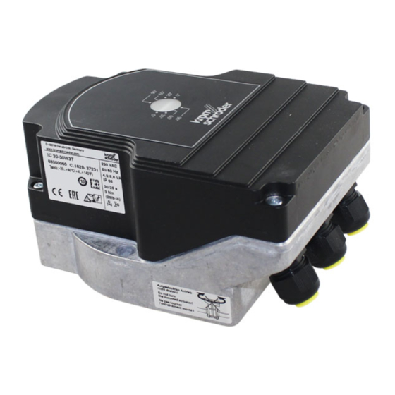
Part designations . . . . . . . . . . . . . . . . . . . . . . . . 2
Type label. . . . . . . . . . . . . . . . . . . . . . . . . . . . . . 2
Installation . . . . . . . . . . . . . . . . . . . . . . . . . . . .
IC 20..E . . . . . . . . . . . . . . . . . . . . . . . . . . . . . . . 4
Input signal . . . . . . . . . . . . . . . . . . . . . . . . . . . . 5
Commissioning. . . . . . . . . . . . . . . . . . . . . . . . . 5
Manual mode facilitates setting . . . . . . . . . . . . . 5
IC 20..E: adapting the adjustment angle to
the input signal in the case of continuous
control . . . . . . . . . . . . . . . . . . . . . . . . . . . . . . . . 6
Accessories . . . . . . . . . . . . . . . . . . . . . . . . . . . 6
"Potentiometer for IC 20" installation set . . . . . . . 6
Adapter set for butterfly valve DKL, DKG . . . . . . 6
"Single application" attachment set. . . . . . . . . . . 7
Heat deflector . . . . . . . . . . . . . . . . . . . . . . . . . . 7
Maintenance . . . . . . . . . . . . . . . . . . . . . . . . . . . 7
Assistance in the event of malfunction . . . . . 7
Technical data . . . . . . . . . . . . . . . . . . . . . . . . . 8
Logistics . . . . . . . . . . . . . . . . . . . . . . . . . . . . . . 9
Certification . . . . . . . . . . . . . . . . . . . . . . . . . . . 9
Contact . . . . . . . . . . . . . . . . . . . . . . . . . . . . . . 0
E
DK
S
N
P
GR
www.docuthek.com
Safety
Safety
Please read and keep in a safe place
Please read through these instructions
carefully before installing or operating. Following the
installation, pass the instructions on to the opera-
tor. This unit must be installed and commissioned
in accordance with the regulations and standards
in force. These instructions can also be found at
www.docuthek.com.
Explanation of symbols
• , , , ... = Action
▷
= Instruction
Liability
We will not be held liable for damage resulting from
non-observance of the instructions and non-com-
pliant use.
Safety instructions
Information that is relevant for safety is indicated in
the instructions as follows:
DANGER
Indicates potentially fatal situations.
WARNING
Indicates possible danger to life and limb.
CAUTION
Indicates possible material damage.
All interventions may only be carried out by qualified
gas technicians. Electrical interventions may only be
carried out by qualified electricians.
Conversion, spare parts
All technical changes are prohibited. Only use OEM
spare parts.
Changes to edition .5
The following chapters have been changed:
-
Accessories
-
Certification
GB-1
Advertisement
Table of Contents

Related Manuals for Krom Schroder IC 20


Summary of Contents for Krom Schroder IC 20
-
Page 1: Table Of Contents
IC 20 ....... . . 4 IC 20..E ....... 4 Changes to edition .5... -
Page 2: Checking The Usage
IC 20 + BVA (for air) IBAF IC 20 + BVAF (for air, clearance-free valve) IC 20 + BVH (for hot air and flue gas) Combination of actuator with linear flow control Type IC 20 + linear flow control IFC ... -
Page 3: Installation
▷ Before opening the unit, the fitter should ground himself. 6 Wire as shown on the connection diagram, see pages 4 (IC 20) and 4 (IC 20..E). 7 Set switch S10 to Automatic mode. ▷ Voltage is applied to terminals 3 and 4. - Page 4 IC 0 1 5 1 6 L1 L1 L1 N ▷ Other circuit layouts produce measurement Three-point step control ▷ In the case of default setting “Closed”: results that are inaccurate and do not remain The control element opens when voltage is ap- stable over a long period of time or are non- plied to terminal 2.
-
Page 5: Input Signal
Press the toggle switch S11 upwards. angle of 45°). Feedback ▷ Terminals 19 and 20: the IC 20..E offers the op- tion of monitoring the current position of the ac- tuator via the continuous 4 – 20 mA output signal. 0 90°... -
Page 6: Control
▷ Maximum input signal = ^ maximum angle, mini- type label. mum input signal = ^ minimum angle. ▷ If the feedback potentiometer is to be retrofit- ▷ The IC 20..E is in Manual mode and the blue ted – see enclosed potentiometer operating LED is lit. instructions. -
Page 7: Single Application" Attachment Set
! The input signal on the 4 – 20 mA setpoint input is < 3 mA. The red LED flashes once. Actuators IC 20 suffer little wear and require little ser- • Check input signal, remedy cable discontinuity. vicing. We recommend a function check once a year. -
Page 8: Technical Data
Duty cycle: 100%. nated with the measures described above? Electrical connection: ! IC 20..E: internal fault. The red LED lights up, Line entrance: 3 x M20 plastic cable glands. the blue LED flashes twice. Typical designed lifetime of the cam switches: •... -
Page 9: Logistics
2 (Part designa- tions). Report any transport damage immediately. Storage The product IC 20 (120 V AC, 230 V AC) meets the Store the product in a dry and clean place. technical specifications of the Eurasian Customs Storage temperature: see page 8 (Technical data). -
Page 10: Contact
Contact Contact If you have any technical questions, please contact your local branch office/agent. The addresses are Elster GmbH available on the Internet or from Elster GmbH. Strotheweg 1, D-49504 Lotte (Büren) Tel. +49 541 1214-0 We reserve the right to make technical modifications Fax +49 541 1214-370 in the interests of progress.
Need help?
Do you have a question about the IC 20 and is the answer not in the manual?
Questions and answers