Table of Contents
Advertisement
05147
D
GB
F
NL
I
TR
CZ
PL
RUS
H
Operating instructions
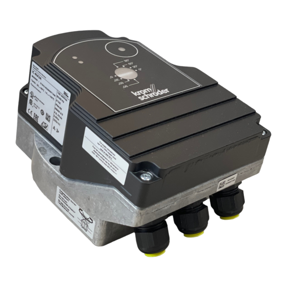
Actuator IC 40
Cert. version 07.18
Contents
Contents
Actuator IC 40. . . . . . . . . . . . . . . . . . . . . . . . . . 1
Contents . . . . . . . . . . . . . . . . . . . . . . . . . . . . . . 1
Safety. . . . . . . . . . . . . . . . . . . . . . . . . . . . . . . . . 1
Checking the usage . . . . . . . . . . . . . . . . . . . . .
Type code . . . . . . . . . . . . . . . . . . . . . . . . . . . . . 2
Part designations . . . . . . . . . . . . . . . . . . . . . . . . 2
Type label. . . . . . . . . . . . . . . . . . . . . . . . . . . . . . 2
Installation . . . . . . . . . . . . . . . . . . . . . . . . . . . .
Connection diagram. . . . . . . . . . . . . . . . . . . . . . 3
Feedback. . . . . . . . . . . . . . . . . . . . . . . . . . . . . . 4
Establishing a connection to a PC . . . . . . . . . 4
Commissioning. . . . . . . . . . . . . . . . . . . . . . . . . 5
LED display . . . . . . . . . . . . . . . . . . . . . . . . . . . . 5
Calibrating the zero position using BCSoft . . . . . 5
Accessories . . . . . . . . . . . . . . . . . . . . . . . . . . . 5
Opto-adapter PCO 200 . . . . . . . . . . . . . . . . . . . 5
Opto-adapter PCO 300 . . . . . . . . . . . . . . . . . . . 5
BCSoft. . . . . . . . . . . . . . . . . . . . . . . . . . . . . . . . 5
Adapter set for butterfly valve DKL, DKG . . . . . . 6
"Single application" attachment set. . . . . . . . . . . 6
Maintenance . . . . . . . . . . . . . . . . . . . . . . . . . . . 6
Technical data . . . . . . . . . . . . . . . . . . . . . . . . . 9
Logistics . . . . . . . . . . . . . . . . . . . . . . . . . . . . . . 9
Certification . . . . . . . . . . . . . . . . . . . . . . . . . . 10
Contact . . . . . . . . . . . . . . . . . . . . . . . . . . . . . . 10
E
DK
S
N
P
GR
www.docuthek.com
Safety
Safety
Please read and keep in a safe place
Please read through these instructions
carefully before installing or operating. Following the
installation, pass the instructions on to the opera-
tor. This unit must be installed and commissioned
in accordance with the regulations and standards
in force. These instructions can also be found at
www.docuthek.com.
Explanation of symbols
• , 1 , , ... = Action
▷
= Instruction
Liability
We will not be held liable for damage resulting from
non-observance of the instructions and non-com-
pliant use.
Safety instructions
Information that is relevant for safety is indicated in
the instructions as follows:
DANGER
Indicates potentially fatal situations.
WARNING
Indicates possible danger to life and limb.
CAUTION
Indicates possible material damage.
All interventions may only be carried out by qualified
gas technicians. Electrical interventions may only be
carried out by qualified electricians.
Conversion, spare parts
All technical changes are prohibited. Only use OEM
spare parts..
Changes to edition 09.16
The following chapters have been changed:
-
Fully revised version
GB-1
Advertisement
Table of Contents

Related Manuals for Krom Schroder IC 40


Summary of Contents for Krom Schroder IC 40
-
Page 1: Table Of Contents
Contents Indicates potentially fatal situations. Actuator IC 40......1 WARNING Contents ......1 Indicates possible danger to life and limb. -
Page 2: Actuator Ic 40
IBAF IC 40 + BVAF (for air, clearance-free valve) ment is designed to adjust volumes of gas and air IC 40 + BVH (for hot air and flue gas) on various appliances and flue gas lines. IC 40 is IBHS IC 40S + BVHS (for hot air and flue gas, adjusted and commissioned using the BCSoft V4.x... -
Page 3: Connection Diagram
▷ Use cables with wire end ferrules. Wiring ▷ Cable cross-section: max. 2.5 mm². ▷ For information on assignment of the inputs WARNING and outputs, see www.docuthek.com → Elster Electric shocks can be fatal! Thermal Solutions → Products → 03 Valves and Before working on electrically live components, –... -
Page 4: Feedback
▷ When connecting to BCSoft, a connection to ▷ A PC or notebook, the BCSoft V4.x program- the IC 40 is established from the PC/notebook. ming software and an opto-adapter PCO 200 or ▷ If a connection fails to be established, the proce- PCO 300 are required for further commissioning,... -
Page 5: Commissioning
Calibrating the zero position using BCSoft 1 After automatic identification via BCSoft, select BCSoft the IC 40 in the “Devices” window by double- For BCSoft software and operating instructions, see clicking on it. The individual program options are www.docuthek.com → Elster Thermal Solutions →... -
Page 6: Adapter Set For Butterfly Valve Dkl, Dkg
Order No.: 74921671 may only be carried out by authorized personnel) Maintenance Actuators IC 40 suffer little wear and require little ser- vicing. We recommend a function check once a year. If the “Service note” option has been activated in... - Page 7 ! Flashes 6 times: saving error for adjustable pa- ? The drive shaft does not move? rameters. ! No permanent voltage supply to the unit. • Carry out reset. • Check supply voltage. • If it is not possible to remedy the fault, send the ! No signal at the unit.
- Page 8 ? The drive shaft moves constantly? ? Feedback potentiometer indicates incorrect ! Current signal fluctuates. values? • Check control loop, if possible attenuate it. ! Connections on the terminal strip mixed up. • Increase the hysteresis and filtering in BCSoft. •...
-
Page 9: Technical Data
(resistive) and max. 2 A (resistive). Disposal Enclosure: Components are to be disposed of separately in IC 40: IP 64, in conjunction with BVH: IP 65, accordance with local regulations. IC 40: Nema 2, in conjunction with BVG, BVA or BVH: Nema 3. -
Page 10: Certification
UL listed Certification Declaration of conformity Underwriters Laboratories – UL 60730-1 “Automatic Electrical Controls for Household and Similar Use”, We, the manufacturer, hereby declare that the prod- UL 60730-2-14 “Automatic Electrical Controls for uct IC 40 complies with the requirements of the fol- Household and Similar Use;...
Need help?
Do you have a question about the IC 40 and is the answer not in the manual?
Questions and answers