Table of Contents
Advertisement
0350481
D
GB
F
NL
I
TR
CZ
PL
RUS
H
Operating instructions
Pressure regulators with solenoid
valve VAD, VAG, VAV, VAH
Flow rate regulator VRH
Pressure regulators with
double solenoid valve
VCD, VCG, VCV, VCH
Cert. version 03.17
Contents
VAD, VAG, VAV, VAH . . . . . . . . . . . . . . . . . . . . 1
Flow rate regulator VRH . . . . . . . . . . . . . . . . . 1
valve VCD, VCG, VCV, VCH . . . . . . . . . . . . . . . 1
Checking the usage . . . . . . . . . . . . . . . . . . . . .
Installing the gas/air control lines . . . . . . . . . 5
Wiring . . . . . . . . . . . . . . . . . . . . . . . . . . . . . . . . 6
Tightness test . . . . . . . . . . . . . . . . . . . . . . . . . . 8
Commissioning. . . . . . . . . . . . . . . . . . . . . . . . . 9
Replacing the actuator . . . . . . . . . . . . . . . . . 11
Maintenance . . . . . . . . . . . . . . . . . . . . . . . . . . 11
Accessories . . . . . . . . . . . . . . . . . . . . . . . . . . 11
Pressure switch for gas DG..VC. . . . . . . . . . . . 11
Bypass/pilot gas valves . . . . . . . . . . . . . . . . . . 12
Attachment block. . . . . . . . . . . . . . . . . . . . . . . 15
Seal set for sizes 1 - 3 . . . . . . . . . . . . . . . . . . . 15
Technical data . . . . . . . . . . . . . . . . . . . . . . . . 16
Logistics . . . . . . . . . . . . . . . . . . . . . . . . . . . . . 18
Certification . . . . . . . . . . . . . . . . . . . . . . . . . . 18
Contact . . . . . . . . . . . . . . . . . . . . . . . . . . . . . . 0
E
DK
S
N
P
GR
www.docuthek.com
Safety
Please read and keep in a safe place
Please read through these instructions
carefully before installing or operating. Following the
installation, pass the instructions on to the opera-
tor. This unit must be installed and commissioned
in accordance with the regulations and standards
in force. These instructions can also be found at
www.docuthek.com.
Explanation of symbols
• , 1 , , 3 ... = Action
▷
= Instruction
Liability
We will not be held liable for damage resulting from
non-observance of the instructions and non-com-
pliant use.
Safety instructions
Information that is relevant for safety is indicated in
the instructions as follows:
DANGER
Indicates potentially fatal situations.
WARNING
Indicates possible danger to life and limb.
CAUTION
Indicates possible material damage.
All interventions may only be carried out by qualified
gas technicians. Electrical interventions may only be
carried out by qualified electricians.
Conversion, spare parts
All technical changes are prohibited. Only use OEM
spare parts.
Changes to edition 0.18
The following chapters have been changed:
-
Installation
-
Technical data
-
Logistics
-
Certification
GB-1
Advertisement
Table of Contents

Related Manuals for Krom Schroder VAD


Summary of Contents for Krom Schroder VAD
-
Page 1: Table Of Contents
VAD, VAG, VAV, VAH ....1 Flow rate regulator VRH ....1... -
Page 2: Pressure Regulators With Solenoid Valve
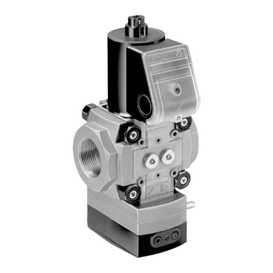
T-product Flow rate regulator with solenoid valve 15 – 50 Nominal inlet and outlet diameter Constant pressure governor VAD for shut-off and pre- Rp internal thread cise control of the gas supply to excess air burners, NPT internal thread atmospheric burners or force draught gas burners. - Page 3 CAUTION 74921990. ▷ Installation position: Please observe the following to ensure that the unit VAD, VAG, VAH: black solenoid actuator in the is not damaged during installation and operation: vertical upright position or tilted up to the hori- – Dropping the device can cause permanent dam- zontal, not upside down.
- Page 4 DN 40 transparent/ Ø 46 mm DN 50 transparent/ Ø 58 mm ▷ If pressure regulator VAD/VAG/VAV 1 is retrofitted upstream of gas solenoid valve VAS 1, a DN 25 differential pressure orifice with outlet opening d = 30 mm (1.18") must be inserted at the outlet of the pressure regulator.
-
Page 5: Installing The Gas/Air Control Lines
Installing the air control line p 1 Install the connection for the air control line in the centre of a straight pipeline which is at least 10 x DN long. ▷ VAG..K: 1 1/8" coupling for plastic hose (internal Regulator with flanges dia. 3.9 mm (0.15"), external dia. 6.1 mm (0.24")) 1 Note direction of flow. -
Page 6: Wiring
– The solenoid actuator heats up during opera- tion. Surface temperature approx. 85°C (approx. 185°F). VAD, VAG, VAV, VAH ▷ Use temperature-resistant cable (> 90°C). 3 We recommend installing a fine-adjusting valve 1 Disconnect the system from the electrical power VMV directly downstream of the regulator in the supply. - Page 7 ▷ When joining two valves, install a cable gland set between the connection boxes. Order No. for cable gland set: Size 1: 74921985, size 2: 74921986, size 3: 74921987. First push through the LV1 N knock-out – then unscrew the cover! ▷...
-
Page 8: Tightness Test
1 = N (–), 2 = LV1 CAUTION Please observe the following to ensure smooth operation: – The closed position indicator is not suitable for frequent cycling operation. – Route valve and closed position indicator cables separately through M20 cable glands or use two separate plugs. -
Page 9: Commissioning
Setting the low-fire rate the factory. ▷ If the burner operates at low-fire rate, the gas/air mixture can be changed by adjusting the adjust- [mbar] ["WC] ing screw “N”. VAD..-25 2.5 – 25 1 – 10 VAD..-50 20 – 50 8 –19.7 VAD..-100 35 –... - Page 10 Final adjustment Pre-setting 6 Set the burner to low fire. 1 Set the minimum and maximum capacity on 7 Conduct a flue gas analysis and set the gas pres- the air control valve in accordance with burner sure at N to the desired analysis value. manufacturer’s specifications.
-
Page 11: Replacing The Actuator
Replacing the actuator Accessories See operating instructions enclosed with spare part Pressure switch for gas DG..VC or see www.docuthek.com. ▷ The pressure switch for gas monitors the inlet pressure p , the outlet pressure p and the in- Maintenance terspace pressure p CAUTION In order to ensure smooth operation, check the tightness and function of the pressure regulator: –... -
Page 12: Bypass/Pilot Gas Valves
Bypass/pilot gas valves Setting the flow rate ▷ The flow rate can be set by turning the flow rate 1 Disconnect the system from the electrical power supply. restrictor (4 mm hexagon socket) ¼ of a turn. Shut off the gas supply. 3 Prepare the installed main valve. -
Page 13: Checking The Bypass/Pilot Gas Valve For Tightness
Mounting the bypass/pilot gas valve VAS 1 VAS 1 for VAx or VAx 3 ▷ Always use a connection pipe F at the inlet of ▷ The connection parts of the main valve remain the main valve. mounted. ▷ For a bypass valve: use connection pipe F 11 Remove the connection parts of the bypass/pilot Ø 10 mm (0.39") at the outlet of the main valve gas valve. -
Page 14: Cable Gland Set For Double Solenoid Valves
1 Disconnect the system from the electrical power supply. Shut off the gas supply. ≤ 1,5 x p u max ≤ 1,5 x p u max ≤ 1,5 x p u max Open the Otworzyć Откройте Ανοίξτε τη Abrir la Otevřít bypass or Aprire la... -
Page 15: Attachment Block
Attachment block Seal set for sizes 1 – 3 ▷ For locked installation of pressure gauge or other ▷ When retrofitting accessories or a second valVario accessories, the attachment block is mounted control or when servicing, we recommend to the solenoid valve. replacing the seals. -
Page 16: Technical Data
Icing, condensation and dew in and on the unit are VAD..-50: 20 – 50 mbar (8 – 19.7 "WC), not permitted. VAD..-100: 35 – 100 mbar (14 – 40 "WC). Avoid direct sunlight or radiation from red-hot Combustion chamber control pressure p (con- surfaces on the unit. - Page 17 VAH, VRH Power consumption: ▷ The inlet pressure must always be higher than the Type Voltage Power 24 V DC 25 W – differential air pressure Δp + max. gas pressure 100 V AC 25 W (26 VA) on burner + pressure loss Δp + 5 mbar (+ 2 "WC). VAx 1 120 V AC 25 W (26 VA)
-
Page 18: Logistics
Components are to be disposed of separately in www.docuthek.com accordance with local regulations. SIL, PL The devices VAD/VAG/VAV/VAH 1 – 3 are suitable for single-channel systems (HFT = 0) up to SIL 2/PL d, and up to SIL 3/PL e when two redundant solenoid valves are installed in a double-channel architecture (HFT = 1), provided that the complete system complies with the requirements of EN 61508/ISO 13849. - Page 19 NFPA 86. VAD, VAG: ANSI/CSA approved* Canadian Standards Association – ANSI Z21.21 and CSA 6.5, ANSI Z21.18 and CSA 6.3 VAD, VAG, VAV: UL listed (for 10 V only) Underwriters Laboratories – UL 429 “Electrically operated valves”. VAD, VAG, VAV: AGA approved* Australian Gas Association...
Need help?
Do you have a question about the VAD and is the answer not in the manual?
Questions and answers