Table of Contents
Advertisement
Quick Links
Advertisement
Table of Contents

Related Manuals for HAWEKA BikeBoss

Summary of Contents for HAWEKA BikeBoss
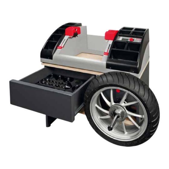
- Page 1 Balancing Stand for Motorbike Wheels Item No. 825 000 000 Operating Instructions (Translation of the Original Operating Instructions) GEB 001 170 HAWEKA AG • Kokenhorststrasse 4 • D-30938 Burgwedel • Tel. +49 5139 8996-0 • Fax +49 5139 8996-222 • www.haweka.com • info@haweka.com...
-
Page 3: Table Of Contents
Description of device ....................8 SCOPE OF DELIVERY .................... 9 Parts list for the BikeBoss and upgrade kits, including accessories ......9 Overview of clamping devices ................. 10 OPERATING PANEL FUNCTION DESCRIPTION ..........11 ... -
Page 4: General Safety Instructions
Balancing Stand BikeBoss 1. General Safety Instructions The balancing stand has been designed and built after careful selection of applicable harmonised standards. Thus, it conforms to the current state-of-the-art technology and provides the highest degree of safety during operation. The balancing stand may only be structurally modified... -
Page 5: Important Instructions For Ensuring Safety When Using
Observe all operating instructions and warning notices that are attached to the device. Labels on the BikeBoss must neither be removed nor made unrecognizable. Missing or illegible labels should be immediately replaced. The user is independently responsible for proper operation and compliance with safety regulations. -
Page 6: Explanation Of Symbols
For correct and safe use of the BikeBoss, ensure that the ambient lighting is a minimum of 300 Lux and a working temperature of 10 °C to +50 °C. -
Page 7: Technical Data
Balancing Stand BikeBoss 2.2 Technical Data Wheel diameter 12 to 23 inch 400 mm Max. wheel width (15.5 inches) Max. weight of wheel when using the 15 mm shaft 15 kg Max. weight of wheel when using the 19.05 mm shaft... -
Page 8: Description Of Device
Thrust washer Power connection: Before using the BikeBoss, the operator must connect the power supply unit (110 / 230 V) supplied to their own power connection and connect the cable to the socket for the power connection on the BikeBoss. -
Page 9: Scope Of Delivery
Balancing Stand BikeBoss 3. Scope of Delivery 3.1 Parts list for the BikeBoss and upgrade kits, including accessories Item No. 825 000 000 BikeBoss “Basic” incl. shaft Ø 15 mm and accessories 825 001 088 1 x BikeBoss balancing stand 825 001 074 1 x Shaft Ø... -
Page 10: Overview Of Clamping Devices
Balancing Stand BikeBoss 3.2 Overview of clamping devices Item No. Clamping device for single arm rocker Figure 860e190 004 Locating sleeve Ducati 860e190 011 Locating sleeve MV Agusta / Honda Locating sleeve Aprilia / BMW / 860e190 012 Yamaha GTS1000... -
Page 11: Operating Panel Function Description
4. Operating Panel Function Description (Fig. 2) When the BikeBoss is switched on, the start menu appears on the screen. On the left side of the screen, the actual functions for the three buttons F1, F2, F3 are indicated. They have different functions, according on the menu selected. -
Page 12: Selection Menu For The Settings
Balancing Stand BikeBoss 4.1 Selection menu for the settings In the start menu, press the button F3. Select Unit (Fig. 3) Select Language On the screen, in the setup menu, the Service-Menu selection is again by using the function buttons. - Page 13 Balancing Stand BikeBoss Button F2: Setting the language Select Unit The program can be set to different Select Language languages. Service-Menu The selection made is activated by (Fig. 9) rotating and pressing the rotary knob. (Fig. 10) The program reverts to the language Select Language selected in the menu setting.
-
Page 14: Preparation For Mounting The Wheel On The Bikeboss
Balancing Stand BikeBoss 5. Preparation for Mounting the Wheel on the BikeBoss 5.1 Clamping the motorbike wheel on the BikeBoss Selection of the correct mounting shaft There are two different mounting shafts for the BikeBoss. (Fig. 13) Shaft Ø 15 mm Shaft Ø... - Page 15 Balancing Stand BikeBoss The second sleeve is inserted into the clamp by the thrust washer and also locked. (Fig. 17) Step II Step I (Fig. 17) To preset, the thrust washer is pushed by the clamp to the rear third of the mounting shaft and locked by moving down the bar on the clamp onto the shaft.
- Page 16 (Fig. 20) Insert the suitable locating disc (Fig. 20) The telescopic rod is suited to connect the shaft and locating disc to the wheel on the BikeBoss at a comfortable working height. (Fig. 21) HAWEKA - BikeBoss...
- Page 17 Do not use force! The thread on the 3-Arm rotary (Fig. 24) handle is visible. Inserting the wheel shaft unit: Before the unit is placed in the BikeBoss, the shaft lowering lever must be put to the top position. (Fig. 25) (Fig. 25)
- Page 18 The unit is now inserted into both bearing blocks of the BikeBoss. The fixed ball bearing on the shaft must be located on the right side of the BikeBoss. (Fig. 26) The bearing blocks in the BikeBoss must be clean.
-
Page 19: Carrying Out A Measurement
Balancing Stand BikeBoss 6. Carrying Out a Measurement 6.1 Record the setting values The position of the measuring tape is set on the BikeBoss for the wheel size to be measured. (Here in the example 17 inch, Fig. 29 (Fig. 29) Repeat this procedure on the other side of the BikeBoss. -
Page 20: Enter The Setting Values
Balancing Stand BikeBoss 6.2 Enter the setting values The BikeBoss is switched on and the main Distance [mm] menu appears on the display. --- ──■■── --- Dyn. Changing between the selection is Diameter [Inch] Menu achieved by rotating and pressing the rotary knob. -
Page 21: First, Start The Measurement
Balancing Stand BikeBoss 6.3 First, start the measurement The values entered appear on the screen of the main menu and the BikeBoss is ready for the first measurement. Make sure that the old compensating weights, any stones, contamination or other foreign objects have been removed from the wheel. - Page 22 The compensation weight is bonded at the bottom, at the 6 o'clock position. The labels are used to detect the correct (Fig. 47) position in the BikeBoss. (Fig. 47) Speed: 90[rpm] After the weights have been attached, a control...
-
Page 23: Measurement Complete, Removing The Wheel
6.4 Measurement complete, removing the wheel When the balancing procedure is completed and the imbalance of the wheel has been rectified, the wheel is removed from the BikeBoss in the reverse sequence. The shaft lowering lever is pushed upwards until the ball bearing rests free in the bearing block. -
Page 24: Calibrating And Maintenance
Balancing Stand BikeBoss (Fig. 52) First, the 3-Arm rotary handle is rotated anticlockwise, so that the unit is released. (Fig. 54) Only then is the bar on the 3-Arm rotary handle opened and pushed downwards away from the shaft. (Fig. 54) Now hold the wheel and pull out the shaft with the pressure disc. - Page 25 Balancing Stand BikeBoss In the service menu, select the button F2 Display for the calibration. Calibration Using the right measuring tape, measure (Fig. 58) to the centre of the wheel and enter the value. (Fig.59 + 60) right: 100 (Fig.
- Page 26 Balancing Stand BikeBoss Step 2 Rotate the wheel until the actual angle Cal. weight 60 gr (Act. angle) agrees with the calibration angle Cal. angle 180 degrees (Cal. angle). (Fig. 65) Act. angle 179 degrees Continue = ENTER (Fig. 65) ...
-
Page 27: Care And Maintenance
Balancing Stand BikeBoss 7.2 Care and maintenance Please note that the BikeBoss, with its clamping devices, is a technical, sensitive measuring device. These components must be used and maintained with great care at all times. Both support surfaces in the bearing blocks must always be kept free of contamination. -
Page 28: Troubleshooting
(Fig. 75) errors when measuring. A correctly balanced wheel when again installed on the BikeBoss (by releasing the wheel + shaft unit and rotating the wheel on the shaft) should not result in imbalance by more than 10 grams. -
Page 29: Spare Parts
Balancing Stand BikeBoss Description Possible causes Troubleshooting Measurement results are not Incorrect wheel data entered Check the wheel data and again realistic enter. Adjustment of the system no Calibration required longer correct. (refer to Pt. 7.1) ... - Page 30 Balancing Stand BikeBoss Spare Parts Part no. Description 825 001 030 Left Storage 825 001 031 Right Storage 825 001 017 Display 825 001 077 Measuring tape 825 001 027 Sliding Scale Marker 825 001 078 Scale HAWEKA - BikeBoss...
-
Page 31: Disposal
Balancing Stand BikeBoss 825 001 017 Main Electrical connection Earthing cable Encoder connection Piezo left (cable length 1.8m Piezo right (cable length 0.6m) 10. Disposal When the device should be disposed of, please contact with your dealer and ask about the requirements for disposal. -
Page 32: Ec Declaration Of Conformity
Balancing Stand BikeBoss 11. EC Declaration of Conformity Haweka AG Kokenhorststrasse 4 30938 Burgwedel Germany herewith declare that the following device described conforms to the EC Directive in its design and construction, as well as in the design as introduced to the market. -
Page 33: Overview Of The Motorbike Data
12. Overview of the Motorbike Data The following lists do not reflect the complete range of applications for the BikeBoss. With this data, we only want to give you assistance for your daily work. Sorted according to manufacturer, the data required for the appropriate motorbike can be quickly found. - Page 34 Balancing Stand BikeBoss Aprilia AXLE DIAMETER Note MODEL front rear Special Adaptors (P/.No.) 15 17 Classic 125 (1995-2000) Dorsoduro 1200 (2011- ) Dorsoduro Factory 25 20 ETV 1000 Caponord (2001-2009) 15 17 ETX 125 (1998-2000) 17 17 ...
- Page 35 Balancing Stand BikeBoss AXLE DIAMETER Note MODEL front rear Special Adaptors (P/.No.) F 650 all Type 17 19 F 650 CS SCARVER (2002-2005) 20 : 1x 860 190 012 For rear Wheel F 700 GS (2013- ) F 800 GS (2008- )
- Page 36 Balancing Stand BikeBoss AXLE DIAMETER Note MODEL front rear Special Adaptors (P/.No.) R 1100 RT (1996-2001) Mono Lever For rear Wheel: 1x 860e150 015 R 1100 S (1998-2005) Mono Lever For rear Wheel: 1x 860e150 015 R 1150 GS (1999-2005)
- Page 37 Balancing Stand BikeBoss DUCATI AXLE DIAMETER Note MODEL front rear Special Adaptors (P/.No.) For rear Wheel: 1x 860e190 004 25 1098 all types (2007-2009) Mono Lever For rear Wheel: 1x 860e190 004 25 1198 all types (2009-2011) Mono Lever For rear Wheel: 1x 860e190 004 25 ...
- Page 38 Balancing Stand BikeBoss DUCATI AXLE DIAMETER Note MODEL front rear Special Adaptors (P/.No.) 17 25 Supersport 800 (2003-2004) 17 25 Supersport 1000 (2003-2007) Harley Davidson AXLE DIAMETER Note MODEL front rear Special Adaptors (P/.No.) Bad Boy (1995-1997) 19,05...
- Page 39 Balancing Stand BikeBoss Harley Davidson AXLE DIAMETER Note MODEL front rear Special Adaptors (P/.No.) Sportster 1200 Low (from 2008) Sportster 1200 Nightster (from 2008) Sportster 1200 Roadster (from 2008) Sportster 883 (from 2008) Sportster 883 (from 2008) Sportster 883 Custom (2005)
- Page 40 Balancing Stand BikeBoss Honda AXLE DIAMETER Note MODEL front rear Special Adaptors (P/.No.) Crossrunner (2011- ) Mono Lever For rear Wheel: 1x 860e190 011 Deauville (2006-2012) DN-01 (2008 - 2011) Mono Lever For rear Wheel: 1x 860 190 016 Fireblade (2006- )
- Page 41 Balancing Stand BikeBoss Hyosung AXLE DIAMETER Note MODEL front rear Special Adaptors (P/.No.) GDI250i GT 125 Naked (2009- 2012 ) GT 250 (all types (2004- ) 15 17 GT 650i (all types 2004- ) 15 15 GV 125 (2000-2010) 15 ...
- Page 42 Balancing Stand BikeBoss Kawasaki AXLE DIAMETER Note MODEL front rear Special Adaptors (P/.No.) Ninja ZX 9 R C+D (2006- ) Ninja ZX-12R (2000-2006) Ninja ZX-6R (1995-1997) Ninja ZX-6R (1998- ) Ninja ZX-6R 636 (2002- ) VN 1500 Classic (all types 1996-2004)
- Page 43 Balancing Stand BikeBoss Kawasaki AXLE DIAMETER Note MODEL front rear Special Adaptors (P/.No.) ZX 750 G: GPZ 750 R (1985) ZX 750 L: ZXR 750 L (1993-1995) ZX 750 P: ZX-7R 750 P Ninja (1996-2002) ZX 900 A: GPZ 900 R (1984-1994)
- Page 44 Balancing Stand BikeBoss AXLE DIAMETER Note MODEL front rear Special Adaptors (P/.No.) Duke 125 (2011- ) Duke 200 (2012- ) Duke 390 (2013- ) Duke I 620 (1994-1998) Duke II 640 E (1998-2007) Freeride 350 (2012- ) LC4 400 (1998)
- Page 45 Balancing Stand BikeBoss Suzuki AXLE DIAMETER Note MODEL front rear Special Adaptors (P/.No.) AN 650 (Roller) (2002- ) Keilwelle Bandit 650 (all types 2005-2006) Bandit 650 (all types 2007- ) B-King (2008-2012) DL 1000 V-Strom (2002-2010) DR 125 (all types 1982- )
- Page 46 Balancing Stand BikeBoss Suzuki AXLE DIAMETER Note MODEL front rear Special Adaptors (P/.No.) SV 650 (all types 2003-2010) SVF 650 Gladius (2009- ) TL 1000 S/R (1997-2000) VL 125 Intruder (2001-2008) VL 1500 LC Intruder (1998- ) VL 250 Intruder (2000-2007)
- Page 47 Balancing Stand BikeBoss Triumph AXLE DIAMETER Note MODELL front rear Special Adaptors (P/.No.) Thruxton 865 (2004- ) Thunderbird 900 (all types) (1995-2004) Tiger 1050 Sport (2013- ) Mono Lever Tiger 1050 Sport / SE (2007-2012) Tiger 800 (2011- ) Tiger 800 XC (2011- )
- Page 48 Balancing Stand BikeBoss Yamaha AXLE DIAMETER Note MODELL front rear Special Adaptors (P/.No.) FZ 1 Fazer (2006- ) FZ 750 (1985-1994) FZ6 600 Fazer/ S2 (2004-2009) FZR 1000 (1987-1988) FZR 1000 (1989-1993) FZR 1000 (1994-1995) FZR 600 (1989-1993) FZR 600 (1994-1995)
- Page 49 Balancing Stand BikeBoss Yamaha AXLE DIAMETER Note MODELL front rear Special Adaptors (P/.No.) XJ 750 (1982-1985) XJ 900 all types (1983-2003) XJR 1200 (1995-1998) XJR 1300 (1999-2001) XJR 1300 (2002- ) XP 500 T max. (2001-2007) XP 500 T max. (2008-2011)
- Page 50 Balancing Stand BikeBoss Yamaha AXLE DIAMETER Note MODELL front rear Special Adaptors (P/.No.) XZ 550 (1982-1984) YBR 125 (2005- ) YZF 1000 R Thunderace (1996-2001) YZF 600 R Thundercat (1996-2002) YZF 750 (1993-1998) YZF R 125 (2008- ) YZF R1 (1998- )
- Page 52 HAWEKA AG Kokenhorststraße 4 30938 Burgwedel Tel. 05139/8996-0 Fax 05139/8996-222 www.haweka.com Info@haweka.com w:\_werkstatt-ausrüstung\8_bikeboss\bedienungsanleitungen\englisch\bikeboss_825-000-000_anleitung_gb_v2_(23zoll)_geb-001-170.docx...
Need help?
Do you have a question about the BikeBoss and is the answer not in the manual?
Questions and answers