
Related Manuals for Mean Well LAD Series


Summary of Contents for Mean Well LAD Series
- Page 1 LAD Series User Manual Load UART DATA PROTOCOL Power Supply Charger Back up AC Grid LAD 120 240 360 600 Series Battery Pack Economical Security/Fire Alarm PSU with Battery Charger/UPS...
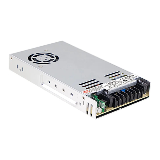
- Page 2 LAD series is an economical AC/DC low profile security power supply with UPS function. Adopting the input range from 90Vac to 264Vac (LAD-120~600:115Vac selectable by switch; LAD-120:90Vac full range input) and supports output 27.6Vdc, 41.5Vdc and 55.2Vdc. With high efficiency up to 86.5% and built-in AC, battery switch for easy maintenance.
-
Page 3: Table Of Contents
Content: 1. Safety Guidelines 2. Introduction 2.1 Model number 2.2 Features Electrical specification 2.4 Safety regulations 2.5 Derating curve & static characteristic curve 2.6 Mechanical specification 3. Installation & Introduction 3.1 Installation requirements 3.2 Torque specification of the fixing holes of the case 3.3 Wiring use 3.4 Installation steps 3.5 Instructions for battery serial and parallel use... -
Page 4: Safety Guidelines
2. Introduction 1.Safety Guidelines 2.1 Model number § Risk of electrical shock and energy hazard. All failure should be examined LAD - 600 by a qualified technician. Please do not remove the case of the power supply by yourself! Blank: TTL signal only §... - Page 5 2 3 Electrical S pecification LAD-120 Series LAD- 0 Series MODEL LAD-240A LAD-240B LAD-240C LAD-240D MODEL LAD-120A LAD-120B LAD-120C LAD-120D OUTPUT NUMBER OUTPUT NUMBER DC VOLTAGE 13.8V 13.8V 27.6V 27.6V 41.5V 41.5V 55 2V 55 2V DC VOLTAGE 13.8V 13.8V 27.6V 27.6V 41.5V...
- Page 6 LAD-360xU Series UART Communication Function Model(U Version) LAD-360x Series TTL Communication Function Model(Blank Version) LAD-360BU LAD-360CU LAD-360DU MODEL LAD-360B LAD-360C LAD-360D MODEL OUTPUT NUMBER OUTPUT NUMBER DC VOLTAGE 27.6V 27.6V 41.5V 41.5V 55 2V 55 2V DC VOLTAGE 27.6V 27.6V 41.5V 41.5V 55 2V...
- Page 7 LAD-600xU Series UART Communication Function Model(U Version) LAD-600x Series TTL Communication Function Model(Blank Version) MODEL LAD-600BU LAD-600CU LAD-600DU MODEL LAD-600B LAD-600C LAD-600D OUTPUT NUMBER OUTPUT NUMBER DC VOLTAGE 27.6V 27.6V 41.5V 41.5V 55 2V 55 2V DC VOLTAGE 27.6V 27.6V 41.5V 41.5V 55 2V...
-
Page 8: Derating Curve & Static Characteristic Curve
LAD-600 Series 2 4 . Safety overview UL62368-1 AS/NZS62368.1 IEC62368-1 TPTC004 2 5 . Derating curve & static characteristic curve 2.5.1 Derating curve INPUT VOLTAGE (VAC) 60Hz 2 6 . Mechanical specification (HORIZONTAL) ℃ AMBIENT TEMPERATURE ( ) LAD-120 Series 2.5. -
Page 9: Installation Introduction
LAD-240/360 Series 3.Installation Introduction 3.1 Installation requirements 32.5 Ÿ Before any installation or maintenance work, please disconnect your LAD 240 360x LAD 240 360xU system from the utility. Ensure that it can't be re-connected inadvertently! BAT. connected Ÿ Keep enough insulation distance between mounting screws and Disconnected S W internal components of power supplies. -
Page 10: Wiring Use
3. Wiring use 3 5 . Serial and parallel connection of battery For input and output terminal block screw specifications, recommended Serial connection: When connect ● torque and wire diameter, please refer to the table below. 2 batteries in series, it doubled t h e o u t p u t v o l t a g e , b u t t h e Battery Battery... -
Page 11: User Interface Panel
4.User Interface Panel Communication function terminal contacts It is used control and status monitoring, etc. For details, 4.1 Panel Description please refer to Chapter 4.2.1. TTL function terminal contacts It is used control and status monitoring, etc. For details, please refer to Chapter 4.2.2. . -
Page 12: Function Description
4.2.2 Connector Pin No. Assignment(CN2)(LAD-120/240/360/600x) 5.Function Description The suitable mating terminal for CN2 is TKP DH2I-2*8 or equivalent. The LAD series equip multiple functions, including four main functions Pin No. Assignment(TTL Signal) Connector Connector Terminal such as DC voltage supplying power to the load, charging the battery, DC- AC OK UPS backup, and communication monitoring interface. -
Page 13: Uart Communication Function(U Version)
● Description of orce 5. UART Communication Function(U version only) start UPS mode (1) In the case of no AC input power supply, when the backup power various fault signals, power supply working status, single switch is OFF, PIN 1 and 2 need to be short-circuited all the time, to battery voltage, main voltage, output voltage and output current to the force the UPS function to start, and keep the battery powered;... - Page 14 ◎ Charging cur ve The way to connect the battery test point: ◎ Charging cur ve Start Start ※LAD-360/600BU bat. bat. Charge Voltage Charge Voltage 100% CC 100% CC BAT1 BAT- BAT+ 10% CC PIN 9 : BAT1 10% CC Charge Current Constant Current Constant Voltage Charge Current...
- Page 15 5.3 Function signals by TTL(Blank version) Battery disconnected/reverse TTL signal: battery detection status When the battery is not connected or reversely connected, the state is TTL Signal is sent out through pins from CN2. high/low level, and the battery status can be known by detecting this External voltage source is required for the TTL signal.
- Page 16 5.3.5 Discharge: Discharge detection 5.4 Communication monitoring function It is used to check whether the system is powered by AC power 5.4.1 UART communication supply or backup power supply. LAD-360/600U series products and external controller (Controller)/PC software can be transmitted through UART. The internal data of a single Between pin 4 and pin 6 Description LAD-360/600U can be set and read through communication, and...
- Page 17 5.4.1.4 Definition of data types 5.4.1. The basic packet structure of the UART communication protocol The data transmission patterns of this agreement are defined as follows: UART communication consists of R/W byte, Data Length, Data address bytes, Data bytes, Error check. Data type Narrate Bytes...
- Page 18 LAD to Controller/PC data sheet LAD_STATUS_H: Data address Bit7 Bit6 Bit5 Bit4 Bit3 Bit2 Bit1 Bit0 The length The data name narrate Numeric range unit bytes byte of the data High byte Reserved Reserved Reserved Reserved Reserved Reserved Reserved Reserved 0x55 0x0010 Instructions for...
- Page 19 5.4.2 Examples of Communications Bit 5 Link_Ctrl: Linkage control status indication 0 = Non-linkage control state The following provides an example of reading and writing to t UART 1 = in the linkage control state communication protocol Bit 6 BAT_OVP : Standby protection status 0 = Non-backup...
- Page 20 LAD_STATUS_L: the status is as follows (gray background content). 0x55 R/W byte R/W decision bit, for reading instructions are 0x55 0x07 Data Length , data length after bit, Bit 7 Bit 6 Bit 5 Bit 4 Bit 3 Bit 2 Bit 1 Bit 0 In this instruction...
- Page 21 Response: 5.4.2.4 Battery voltage Brief description: Battery voltage read instructions R/W byte Data Length Data address bytes Data bytes CRC-8 For example: to read the battery voltage to which the LAD-360DU 0x55 0x05 0x00 20 0x08 FE 0x97 connected 0x55 R/W byte R/W decision bit, for reading instructions are 0x55 Request:...
- Page 22 5.4.2.5 Single cell battery voltage 0xAA : Transmit data CRC-8 error detection code, refer to the description Brief description: Battery voltage read instructions CRC-8 5.4.1.3 CRC-8 error detection code for the response is calculated by the For example: to read the voltage of a single cell connected to the LAD's own MCU LAD-360DU Request:...
- Page 23 5.4.2. Backup removal control 5.4.2. Buzzer Shutdown Control Brief description: Backup removal control, which is invalid when forced Brief description: Turn off the LAD buzzer function, the corresponding to start instructions are as follows: or example, turn off the standby power supply function of the LAD- 01: Buzzer off 360DU...
-
Page 24: Protections And Failure Correction
Output wire diameter is too thin Choose appropriate thickness of wire after recycling AC power and 3 minutes of cold standby. Incorrect charging curve setting Reconfirm the battery charging curve Note: Please contact MEAN WELL's distributor if above faulty conditions are not corrected. -
Page 25: Warranty
※ MEAN WELL reserves the right to change the content of this manual. Please refer to the latest version of our manual on our website. https:// www.meanwell.com MEAN WELL WEB User's Manual...
Need help?
Do you have a question about the LAD Series and is the answer not in the manual?
Questions and answers