SATO D508 Service Manual
Hide thumbs
Also See for D508:
- Operator's manual (60 pages) ,
- Programming reference manual (290 pages) ,
- Parts list (13 pages)
Table of Contents
Advertisement
Quick Links
Advertisement
Table of Contents
Troubleshooting

Related Manuals for SATO D508


Summary of Contents for SATO D508
- Page 1 D508/D512 PRINTER SERVICE MANUAL PN: 9001178...
- Page 2 SATO America, Inc. 10350A Nations Ford Road Charlotte, NC 28273 Main Phone: (704) 644.1650 Technical Support: (704) 644.1660 Technical Support Fax: (704) 644.1661 E-Mail: satosales@satoamerica.com techsupport@satoamerica.com www.satoamerica.com PN: 9001178...
-
Page 3: Table Of Contents
Table of Contents Overview Introduction ............................1-3 Unpacking ............................. 1-4 Printer Part Names ..........................1-5 Setting Up The Printer .......................... 1-6 Loading Media ............................1-7 Label Sensing ............................1-9 3.1 Operating Panel ..........................1-10 Configuration: The Rear Panel ......................1-11 The Configuration Panel ........................ - Page 4 Problem: Print Start Position Is Incorrect Vertically ................3-13 Problem: Print Start Position Is Incorrect Horizontally ................ 3-14 Problem: White Lines Appear In Printed Labels ................3-14 Problem: Labels are Not Being Dispensed Properly By The Optional Dispenser Unit ...... 3-15 Problem: The Cutter Is Not Working ....................
-
Page 5: Overview
Unit 1: Overview OVERVIEW SATO D508/D512 Service Manual Page 1-1... - Page 6 This Service Manual contains information about the specifications, replacement procedures, checking/calibration procedures, and troubleshooting of common problems associate with the D508/D512. A total of four topics are covered herein, and they are organized as follows: Section 1: Overview Section 2: Basic and Interface Specifications...
-
Page 7: Introduction
The major difference in the D508 and the D512 printers is the resolution of the print head. The D508 with its 203 dpi head provides an economical labeling solution for most applications. It can print labels up to four inches wide. -
Page 8: Unpacking
The following parts shown here are representative only. Due to regional requirements and our policy of continual improvement, your printer may not be packed with the exact parts as shown here, but the unpacking steps are similar. Printer AC adaptor and cable User documentation and software package (where applicable) SATO D508/D512 Service Manual Page 1-4... -
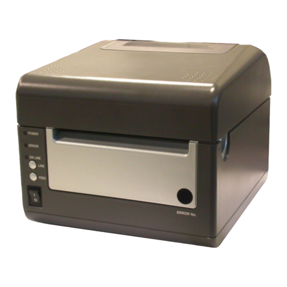
Page 9: Printer Part Names
Error Status LED LEDs Front cover (allows access to optional cutter unit, DIP switches and potentiometers) Thermal Print Head assembly Label Holders Label Sensor Mini Screwdriver Label Holder Release Knob Platen Assembly Optional Cutter Page 1-5 SATO D508/D512 Service Manual... -
Page 10: Setting Up The Printer
6. Configure the printer for label width and operating mode using the instructions in this section. 7. Press the printer power button to the ON (I) position. 8. Print a test label to verify the printer is set up and operating correctly. SATO D508/D512 Service Manual Page 1-6... -
Page 11: Loading Media
LOADING MEDIA The SATO D508/D512 printer can print to direct thermal die-cut labels, tags or continuous media. The media supply can be either in Roll or Fanfold format. Roll Media Roll media should be between 0.98" (25 mm) and 4.3" (110 mm) in width and wound face-out on a core with a minimum internal diameter of 1.6"... - Page 12 Top apart from each other. Cover 5. Route the label material through the Sensor Assembly and over the Platen. Load fanfold paper SATO D508/D512 Service Manual Page 1-8...
-
Page 13: Label Sensing
Fanfold-label path Overview of the fanfold-paper loading path LABEL SENSING The SATO D508/D512 uses label Gap (see-through) or Eye-Mark (reflective) sensing. The Sensor Assembly is located on the left edge of the media and is automatically positioned by the Paper Guides. -
Page 14: 3.1 Operating Panel
Press this button to eject one label in OFFLINE mode. Hold this button down while power is applied, to print a printer status label. POWER SWITCH A two position switch for turning the printer ON (I) or OFF (0). SATO D508/D512 Service Manual Page 1-10... -
Page 15: Configuration: The Rear Panel
All of the printer cable connectors are located on the Rear Panel, as follows. Fanfold-label Loading Slot Remove this panel to route fanfold paper into the printer Interface Power Slot Connector (IEEE1284 for DC power Parallel input from the Interface supplied AC Connector Adapter shown) Page 1-11 SATO D508/D512 Service Manual... -
Page 16: The Configuration Panel
Configuration Switch off position after printing is complete. Before the next label is printed, the paper is pulled back in to the first print line position. Cutter mode - Enables the Cutter option if installed. SATO D508/D512 Service Manual Page 1-12... -
Page 17: Switch 4: Unused
OFF position, VR1 will adjust the media tear- Print Darkness off / cut (backfeed distance) offset value over a range of +/- 3.75 mm. When placed in the ON position, VR1 will adjust the print darkness range. Configuration Switch Page 1-13 SATO D508/D512 Service Manual... - Page 18 When OFF, the printer will Enabled accept and process the data stream in a normal fashion. Configuration Switch Switch 8: Unused DSW8 Mode This switch is reserved for future use. Configuration Switch SATO D508/D512 Service Manual Page 1-14...
-
Page 19: Offsets
The following should be used as starting points for establishing the three Offset values: Mode Length of Offset (mm) Length of Offset (in) Print head resolution CUTTER 17.9 0.70 143/215 TEAR-OFF 29.2 1.15 234/350 Page 1-15 SATO D508/D512 Service Manual... -
Page 20: Potentiometer Adjustments
Adjusting the Label Pitch with VR4 will affect the stop position of the label and the cut/tear-off positions. Moved with Leading Edge of Positive (+) Offset Label as detected to print on trailing by the sensor edge of label SATO D508/D512 Service Manual Page 1-16... - Page 21 Adjustment of the Print Darkness using VR1 will affect the darkness in all the <ESC>#E command code ranges; that is, if the print darkness is adjusted with VR1 for lighter print, the darkness will be lighter in all the Print Darkness ranges selected by the command code. Page 1-17 SATO D508/D512 Service Manual...
-
Page 22: Data Dump Diagnostic Label
5. The data received is printed on the label. 6. Place DSW7 in the OFF position. 7. Turn the printer OFF and then back ON to place it back in the normal print mode. SATO D508/D512 Service Manual Page 1-18... -
Page 23: Printing Test Labels
6. To remove the printer from the Test Label mode, power the printer OFF. Note: Depending on the version of your printer’s onboard software, the appearance of your test printout may be different from that shown here. Page 1-19 SATO D508/D512 Service Manual... -
Page 24: Printing Factory/Service Test Prints
To remove the printer from the Factory/Service Print Test mode, remove power by placing the POWER switch in the OFF position. Note: Depending on the version of your printer’s onboard software, the appearance of your test printout may be different from that shown here. SATO D508/D512 Service Manual Page 1-20... -
Page 25: Basic And Interface Specifications
Unit 2: Interface Specifications BASIC AND INTERFACE SPECIFICATIONS • Basic Printer Specs • Interface Specs D508/D512 Service Manual Page 2-1... -
Page 26: 1.1 Basic Printer Specifications
Sensor not used Eye Mark Fixed, 0.25" (6.3 mm) from left label edge. 0.12” (3 mm) wide x mini- mum 0.5” (12 mm) in length from left label edge. *All specifications subject to change without notice. Page 2-2 D508/D512 Service Manual... -
Page 27: General Specifications (Cont'd)
RS232C (9600 to 57.6K bps) Hardware Flow Control (Ready/Busy) Software Flow Control (X-On/X-Off) Bi-directional Status USB (Option) USB Specification Version 1.1 LAN (Option) 10/100 Base-T RFID (Option) 13.56 MHz band, TBA Wireless LAN (Option) *All specifications subject to change without notice. D508/D512 Service Manual Page 2-3... - Page 28 Operation environment 0~35°/30~80% (without condensation) Storage environment -5~45°/20~80% (without condensation) REGULATORY APPROVALS Safety USA : UL(UL60950-1) CANADA : C-UL(CSA C22.2 No.60950-1-3) Europe : TUV(EN60950-1), CE EMC/EMS USA : FCC15B (ClassB) Europe : EN55022 ClassB, EN61000-3-2, EN61000- 3-3,EN55024 Page 2-4 D508/D512 Service Manual...
- Page 29 TCP/IP Protocol Interface option. Factory or User installable. USB Interface Universal Serial Bus Interface option. Factory or User installable. RFID To be announced Wireless LAN Interface 802.11 b/g *All specifications subject to change without notice. D508/D512 Service Manual Page 2-5...
-
Page 30: Interface Types
INTERFACE SPECIFICATIONS INTERFACE TYPES The SATO D508/D512 printer can be ordered with any of the interfaces described in this section. The user can specify the desired interface at the time of placing an order. Thereafter, if the user needs to change the interface, it is a simple matter of purchasing a suitable interface card from a SATO dealer. -
Page 31: The Receive Buffer
Single Job Buffer The printer receives and prints one job at a time. Each job must not exceed 2.95MB. D508/D512 Service Manual Page 2-7... - Page 32 All printer error conditions (i.e., label out, Time-out Error, etc) will cause the printer to go busy (DTR "low" or X-Off) until the problem is corrected and the printer is placed on-line. The printer will also be busy if taken off-line from the front panel. Page 2-8 D508/D512 Service Manual...
-
Page 33: Ieee1284 Parallel Interface
To Host INIT From Host AUTOFD (1) To Host FAULT To Host Not Used Not Used Logic Gnd Not Used Frame Ground Not Used +5V(Z=24Kohm) To Host From Host SELECTIN Signals required for IEEE1284 mode D508/D512 Service Manual Page 2-9... -
Page 34: Rs-232C Interface
Connector DB-25S (Female) Cable DB-25P (Male), 50 ft. maximum length. For cable configuration, refer to Cable Requirements appropriate to the RS232C protocol chosen. Signal Levels High = +5V to +12V Low = -5V to -12V Page 2-10 D508/D512 Service Manual... -
Page 35: Rs-232C Interface Signals
Sin- gle Job Buffer mode. It will also go low when the data in the buffer reaches the Buf- fer Near Full level. Cable Requirements D508/D512 Service Manual Page 2-11... -
Page 36: Universal Serial Bus Interface
Upon power up if no error conditions are present, the printer will continually send X-On characters at five millisecond intervals until it receives a transmission from the host. UNIVERSAL SERIAL BUS INTERFACE Page 2-12 D508/D512 Service Manual... -
Page 37: Local Area Network Interface
The driver must be loaded onto the host computer and configured to run one of the supported protocols. Details for setting up the Wireless 802.11 LAN Interface are contained in the documentation that is supplied with the interface card. D508/D512 Service Manual Page 2-13... - Page 38 Unit 2: Interface Specifications This page is left blank intentionally D508/D512 Service Manual Page 2-14...
-
Page 39: Troubleshooting
Unit 3: Troubleshooting TROUBLESHOOTING • Error Signals • Troubleshooting Table • Interface Troubleshooting • Test Print Troubleshooting SATO D508/D512 Service Manual Page 3-1... - Page 40 Serial Overrun error 1) Ensure correct flow control 2) Retry 1 Beep LAN Time Out error 1) Check Interface card 2) Check connections 3) Replace the above 3 Beeps Serial Font/Graphic error Ensure correct data stream Page 3-2 SATO D508/D512 Service Manual...
- Page 41 Ensure print head wiring harness is connected on each end No voltage output Test power supply and replace as necessary Damaged print head Replace print head Damaged electronics Replace circuit board Interface problems Check. Refer to relative instructions below SATO D508/D512 Service Manual Page 3-3...
- Page 42 INCORRECT LABEL POSITIONING Incorrect sensor selection Ensure the correct sensor is selected Improper sensor adjustment Adjust as required Incorrect media in use Ensure the correct media is being used Data input error Ensure correct data stream Page 3-4 SATO D508/D512 Service Manual...
- Page 43 0Dhex and/or 0Ahex (carriage return and line feed) characters through- out. Replace the interface board with another to isolate the problem. Replace the interface board permanently if determined to be the problem. SATO D508/D512 Service Manual Page 3-5...
- Page 44 Click on the Device Manager tab. Ensure that the View Device By Type is checked. Scroll to printer driver for your SATO device. Ensure that errors do not exist. Reinstall the driver as required. Reboot the PC and the printer.
-
Page 45: Troubleshooting Flowcharts
Unit 3: Troubleshooting TROUBLESHOOTING FLOWCHARTS PROBLEM: PRINTER DOES NOT POWER UP See Pg 5-10 See Pg 4-5 SATO D508/D512 Service Manual Page 3-7... -
Page 46: Problem: Label Does Not Feed Outward In A Straight Path
PROBLEM: LABEL DOES NOT FEED OUTWARD IN A STRAIGHT PATH See Pg 4-3 PROBLEM: PRINTER DOES NOT PRINT Page 3-8 SATO D508/D512 Service Manual... - Page 47 Unit 3: Troubleshooting PROBLEM: PRINTER DOES NOT PRINT Pg 4-2 Pg 4-5 SATO D508/D512 Service Manual Page 3-9...
-
Page 48: Problem: Printer Does Not Feed Labels
PROBLEM: PRINTER DOES NOT FEED LABELS See Pg 1-13 to 1-15 See Pg 4-3 See Pg 4-13 See Pg 4-5 Page 3-10 SATO D508/D512 Service Manual... -
Page 49: Problem: Printer Does Not Stop At The Correct Position
Unit 3: Troubleshooting PROBLEM: PRINTER DOES NOT STOP AT THE CORRECT POSITION See Pg 1-13 to 1-15 See Pg 5-8 - 5-9 See Pg 4-5 PROBLEM: WIRELESS LAN PRINTER IS NOT PRINTING SATO D508/D512 Service Manual Page 3-11... -
Page 50: Problem: Printing Is Too Dark
PROBLEM: PRINTING IS TOO DARK See Pg 5-4 Pg 5-4 Pg 4-2 Pg 4-5 PROBLEM: PRINTING IS TOO LIGHT ON ONE SIDE See Pg 4-3 See Pg 4-2 Page 3-12 SATO D508/D512 Service Manual... -
Page 51: Problem: Print Start Position Is Incorrect Vertically
Unit 3: Troubleshooting PROBLEM: PRINT START POSITION IS INCORRECT VERTICALLY See Pg 5-8 - 5-9 See Pg 5-2 SATO D508/D512 Service Manual Page 3-13... -
Page 52: Problem: White Lines Appear In Printed Labels
PROBLEM: PRINT START POSITION IS INCORRECT HORIZONTALLY See Pg 4-3 PROBLEM: WHITE LINES APPEAR IN PRINTED LABELS See Pg 4-2 Page 3-14 SATO D508/D512 Service Manual... - Page 53 Unit 3: Troubleshooting PROBLEM: LABELS ARE NOT BEING DISPENSED PROPERLY BY THE OPTIONAL DISPENSER UNIT SATO D508/D512 Service Manual Page 3-15...
-
Page 54: Problem: The Cutter Is Not Working
PROBLEM: THE CUTTER IS NOT WORKING See Pg 1-13 to 1-15 See Pg 4-17 PROBLEM: THE CUTTER IS NOT WORKING See Pg 4-17 Page 3-16 SATO D508/D512 Service Manual... -
Page 55: Test Print Troubleshooting
Press LINE Large Label / Small Label Press FEED Prints large Prints small labels. labels. Press FEED Printing is paused. Press FEED Printing commences. Switch POWER off to exit Figure 3-1, Test Label Printing SATO D508/D512 Service Manual Page 3-17... - Page 56 NOTE: The only print problem that the following sample test label does not display is fading of print image from one side of the label to the other. This is the result of improper print head balance. Figure 3-2, Sample Test Label Page 3-18 SATO D508/D512 Service Manual...
-
Page 57: Data Dump Diagnostic Label
POWER = OFF DSW7 = ON Power = ON Printer receives data and prints. DSW7 = OFF Switch POWER off and the on again to return to normal mode. Figure 3-3, Data Dump Diagnostic Mode SATO D508/D512 Service Manual Page 3-19... -
Page 58: Printing Factory/Service Test Labels
Press LINE Large Label / Small Label Press FEED Prints large Prints small labels. labels. Press FEED Printing is paused. Press FEED Printing commences. Switch POWER off to exit Figure 3-4, Factory/Service Test Label Printing Page 3-20 SATO D508/D512 Service Manual... - Page 59 Unit 3: Troubleshooting This page is left blank intentionally SATO D508/D512 Service Manual Page 3-21...
- Page 60 Unit 3: Troubleshooting SATO D508/D512 Service Manual Page 3-22...
-
Page 61: Replacement Procedures
Print Head • Platen Roller • Fuse • Main Circuit Board • Panel Board • Label Sensor Board • Label Sensor • Cover Open Sensor • Drive Motor • Drive Gear • Cutter Replacement SATO D508/D512 Service Manual Page 4-1... -
Page 62: Print Head Replacement
Press inward and raise upward, the upper portion of the print head until it locks into position. Load some media, close the cover, and do a test print to confirm proper function. Figure 4-1, Print Head Replacement Page 4-2 SATO D508/D512 Service Manual... -
Page 63: Platen Roller Replacement
Lower the dispenser bar (5) and reattach the gear cover (3). Load some media, close the cover, and do a test print to ensure proper function. Figure 4-2, Platen Roller Replacement ACCESSING THE MAIN BOARD SATO D508/D512 Service Manual Page 4-3... - Page 64 Remove the bottom housing cover (See Figure below) by removing four screws. Put the screws in a safe place so that they can be used to re-secure the bottom housing cover when servicing is complete. Screw x4 Figure 4-3, Removing Bottom Cover Page 4-4 SATO D508/D512 Service Manual...
-
Page 65: Fuse Replacement
Attach a replacement fuse (1) to the metal holders (3) on the main circuit board (2). Attach base cover to the housing cover. Load some media, and run some tests to confirm proper function. Figure 4-4, Fuse Replacement SATO D508/D512 Service Manual Page 4-5... -
Page 66: Main Circuit Board Replacement
NOTE: Each wiring harness connector is different from the others. To reconnect the wiring harnesses, simply match mating halves. Attach the base cover to the housing cover. Load some media, and run some tests to confirm proper function. Figure 4-5, Main Circuit Board Replacement Page 4-6 SATO D508/D512 Service Manual... -
Page 67: Panel Board Replacement
Attach the base cover to the housing cover. Load some media, and run some tests to confirm proper function. Figure 4-6, Panel Board Replacement SATO D508/D512 Service Manual Page 4-7... -
Page 68: Relay Board (Label Sensor Board) Replacement
As the main signal cable of the relay board (9) is soldered on, you need to disconnect the other end of the cable from the main board by the following steps. NOTE: Each wiring harness connector is different from the others. To reconnect the wiring harnesses, simply match mating halves. Page 4-8 SATO D508/D512 Service Manual... - Page 69 Place the left-side media holder (6) (See Figure 4-7a) into the printer (3) along with the gear (5) and secure using a screw (4). Secure the bar (2) to the printer (3) using a screw (1). Load some media, and run some tests to confirm proper function. SATO D508/D512 Service Manual Page 4-9...
-
Page 70: Label Sensor Replacement
Remove one screw (7) that secures the sensor cover (8) to the left-side media holder (6). Remove one screw (9) that secures the sensor (10) to the sensor cover (8). Figure 4-8a, Label Sensor Replacement Page 4-10 SATO D508/D512 Service Manual... - Page 71 Place the media holder (6) into the printer (3) along with the gear (5) and secure using a screw (4). Secure the bar (2) to the printer (3) using a screw (1). Load some media, and run some tests to confirm proper function. Figure 4-8b, Label Sensor Replacement SATO D508/D512 Service Manual Page 4-11...
-
Page 72: Cover Sensor Replacement
Detach the defective sensor from the printer and route the replacement sensor in its place. Connect the replacement sensor to the main board (6) and re-secure the board (6) to the printer (8) using five screws (7). Page 4-12 SATO D508/D512 Service Manual... - Page 73 12 Return the cable cover (3) to the top housing cover (1) and secure it using two screws (2). 13 Load some media, and run some tests to confirm proper function. Figure 4-9b, Cover Sensor Replacement SATO D508/D512 Service Manual Page 4-13...
-
Page 74: Drive Motor Replacement
Remove the two screws (5) that secure the drive train (6) to the printer (3). Remove the drive train (6) from the printer (3) and disconnect the motor’s wiring harness. Figure 4-10a, Drive Motor Replacement Page 4-14 SATO D508/D512 Service Manual... - Page 75 Reconnect all the appropriate wiring harnesses to the main circuit board (2). Attach the base cover to the housing cover. Load some media, and run some tests to confirm proper function. Figure 4-10b, Drive Motor Replacement SATO D508/D512 Service Manual Page 4-15...
-
Page 76: Drive Gear Replacement
Remove the two screws (5) securing the drive train (6) to the printer (3). Withdraw the drive train (6) from the printer (3) and disconnect the motor’s wiring harness. Figure 4-11a, Drive Gear Replacement Page 4-16 SATO D508/D512 Service Manual... - Page 77 Reconnect all the appropriate wiring harnesses to the main circuit board (2). Attach the base cover to the housing cover. Load some media, and run some tests to confirm proper function. Figure 4-11b, Drive Gear Replacement SATO D508/D512 Service Manual Page 4-17...
-
Page 78: Cutter Assembly
If this is performed correctly, the two mounting holes will be properly aligned for the attaching hardware. Lower the dispenser bar (4) and apply the front cover (2). Perform steps 7 through 13 to install/replace the cutter blade as the situation requires. Page 4-18 SATO D508/D512 Service Manual... - Page 79 Remove two screws (12) securing upper plate (13) to lower plate (14) and separate. Figure 4-12b, Cutter Blade Installation Install the cutter blade (15) between the plates (14) and (13), secure it using two screws (12). SATO D508/D512 Service Manual Page 4-19...
- Page 80 Unit 4: Replacement Procedures This page is left blank intentionally SATO D508/D512 Service Manual Page 4-20...
-
Page 81: Checks/Adjustment Procedures
Print Darkness • Printer Counter Clear • Cutter Counter Clear • Test Print Counter Clear • Cut Position • Paper Sensor Sensitivity • Gap Sensor Sensitivity • Eye-Mark Sensor Adjustment • Power Supply Checks SATO D508/D512 Service Manual Page 5-1... - Page 82 VR4 will affect the stop position of the label and the cut/tear-off positions. Moved with Leading Edge of Positive (+) Offset Label as detected to print on trailing by the sensor edge of label Page 5-2 SATO D508/D512 Service Manual...
- Page 83 NOTE: Press the LINE button to test print a large label and the FEED button to test print a small label. Pressing the FEED button terminates printing activity. Print at least two labels to ensure the clear process was successful. SATO D508/D512 Service Manual Page 5-3...
- Page 84 VR1 for lighter print, the darkness will be lighter in all the Print Darkness ranges selected by the command code. Figure 5-1, Test Panel Page 5-4 SATO D508/D512 Service Manual...
- Page 85 Darkness Printer Test Panel Dip Switch Complex Test Connector Potentiometers Set the dial to the correct pin number Test Module Dial Connect ground probe here Connect positive probe here Figure 5-2, Test Module Usage SATO D508/D512 Service Manual Page 5-5...
- Page 86 Press the LINE button to test print a large label and the FEED button to test print a small label. NOTE: Pressing the FEED button pauses test printing activity. Allow a minimum of two labels to be printed before terminating to ensure the clear process was successful. Page 5-6 SATO D508/D512 Service Manual...
-
Page 87: Test Print Counter Clear
Use the printed test label to determine the required direction for the desired adjustment. Adjust the VR1 potentiometer accordingly and repeat the test print process. Repeat steps 3 through 5 until a proper offset adjustment is achieved. SATO D508/D512 Service Manual Page 5-7... -
Page 88: Eye Mark / Paper End Sensor Sensitivity
Adjust the VR2 potentiometer until the multimeter displays a value of +0.5 V ± 0.2 V. Remove the label from the sensor and confirm that the voltage displayed is now 0.9 volts above the previous reading. Repeat steps 7 through 9 until an acceptable sensitivity level is established. Page 5-8 SATO D508/D512 Service Manual... -
Page 89: Gap Sensor Sensitivity
Confirm the voltage displayed on the multimeter is now +1.0 volts or greater. 10 Repeat steps 7 through 10 until an acceptable sensitivity level is established. 11 Repeat steps 7 through 10 until a acceptable sensitivity level is established. SATO D508/D512 Service Manual Page 5-9... -
Page 90: Power Supply Checks
Test Points Voltage Range + 5.0 V Pin 3 (GNC) of CN3 +4.8 V to +5 V Pin 4 of CN3 Power Supply Connector If the voltages are not correct, replace the power supply. Page 5-10 SATO D508/D512 Service Manual...
Need help?
Do you have a question about the D508 and is the answer not in the manual?
Questions and answers