
Related Manuals for Sauder Moderna 5427968


Summary of Contents for Sauder Moderna 5427968
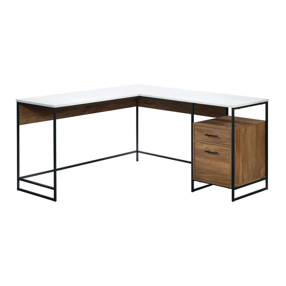
- Page 1 The original desktop. Moderna L-Shaped Desk NOTE: THIS INSTRUCTION BOOKLET CONTAINS IMPORTANT SAFETY INFORMATION. PLEASE READ AND KEEP FOR FUTURE REFERENCE. Model 5427968 English pg 1-28 Lot # 553337...
- Page 2 Table of Contents Assembly Tools Required Part Identification No. 2 Phillips Screwdriver Hardware Identification Tip Shown Actual Size Hardware Usage Guide Assembly Steps 6-28 Français 29-32 Español 33-36 Safety 37-38 Warranty Now you know Part Identification our ABCs. å While not all parts are labeled, some of the parts will have a label or an inked letter on the edge to help distinguish similar parts from each other.
- Page 3 Part Identification Page 3...
- Page 4 Hardware Identification å Screws are shown actual size. You may receive extra hardware with your unit. (EXTENSION SET SHOWN SEPARATED) (EXTENSION SET SHOWN SEPARATED) NARROW EXTENSION NARROW EXTENSION WIDE EXTENSION WIDE EXTENSION RAIL - 2 SLIDE - 2 RAIL - 2 SLIDE - 2 CAM SCREW - 17 HIDDEN CAM - 17...
- Page 5 Hardware Usage Guide HOW TO USE A HIDDEN CAM & CAM SCREW OR CAM DOWEL NOTE: Various CAM SCREWS or a CAM DOWEL may be used. Turn the CAM SCREW or gently tap the CAM DOWEL until the shoulder is against the surface of the part.
- Page 6 Step 1 å Assemble your unit on a carpeted floor or on the empty carton to avoid scratching your unit or the floor. å Push four HIDDEN CAMS (6) into the ENDS (C and D). å Turn two CAM SCREWS (5) into the exact holes shown in the ENDS (C and D).
- Page 7 Step 2 å Separate the NARROW EXTENSION SLIDES (2) from the NARROW EXTENSION RAILS (1) as shown in the upper diagram below. Be prepared, the parts are greasy. å Fasten the NARROW EXTENSION RAILS (1) to the ENDS (C and D). Use six 1/2" FLAT HEAD SCREWS (21) through the exact holes shown.
- Page 8 Step 3 å Separate the WIDE EXTENSION SLIDES (4) from the WIDE EXTENSION RAILS (3) as shown in the upper diagram below. Be prepared, the parts are greasy. å Fasten the WIDE EXTENSION RAILS (3) to the ENDS (C and D). Use six 1/2" FLAT HEAD SCREWS (21) through the exact holes shown.
- Page 9 Step 4 å Push two HIDDEN CAMS (6) into the BRACE (E). å Insert two WOOD DOWELS (7) into the ENDS (C and D). å Fasten the ENDS (C and D) to the BRACE (E). Tighten two HIDDEN CAMS. å NOTE: Be sure the WOOD DOWELS in the ENDS insert into the BRACE.
- Page 10 Step 5 å Turn four CAM SCREWS (5) into the SHELF (A). å Insert four WOOD DOWELS (7) into the SHELF (A). å Fasten the SHELF (A) to the ENDS (C and D). Tighten four HIDDEN CAMS. å NOTE: Be sure the WOOD DOWELS in the SHELF insert into the ENDS.
- Page 11 Step 6 å Insert eight WOOD DOWELS (7) into the ENDS (C and D) and BACK (F). å Insert the WOOD DOWELS in one edge of the BACK (F) into the holes in the SHELF (A). å Fasten the BOTTOM (B) to the ENDS (C and D). Use four 1-9/16" PAN HEAD SCREWS (14). å...
- Page 12 Step 7 å Fasten the LOWER END BRACES (HH) to the BOTTOM (B). Tighten four 1" HEX HEAD SCREWS (17) using the L-WRENCH (12). 1" HEX HEAD SCREW (4 used in this step) Page 12...
- Page 13 Step 8 å Fasten the FRAMES (FF and GG) to the LOWER END BRACES (HH). Tighten four 1" HEX HEAD SCREWS (17) using the L-WRENCH (12). å Fasten the UPPER END BRACE (EE) to the FRAMES (FF and GG). Tighten two 1" HEX HEAD SCREWS (17) using the L-WRENCH (12).
- Page 14 Step 9 å Fasten the LOWER SHORT BRACE (CC) to the LEG (Z). Tighten two 1/2" HEX HEAD SCREWS (20) using the L-WRENCH (12). 1/2" HEX HEAD SCREW (2 used in this step) Page 14...
- Page 15 Step 10 å Push three HIDDEN CAMS (6) into the SHORT PANEL (X). å Fasten the SHORT PANEL (X) to the LEG (Z). Tighten two 1-7/8" HEX HEAD SCREWS (13) using the L-WRENCH (12). 1-7/8" HEX HEAD SCREW (2 used in this step) Arrow Page 15...
- Page 16 Step 11 å Carefully stand the FRAME assembly upright. å Fasten the SHORT PANEL (X) to the CENTER FRAME (GG). Tighten two 1-7/8" HEX HEAD SCREWS (13) using the L-WRENCH (12). å Fasten the LOWER SHORT BRACE (CC) to the CENTER FRAME (GG). Tighten one 1"...
- Page 17 Step 12 å Push four HIDDEN CAMS (6) into the LONG PANEL (V). å Fasten the LEFT FRAME (Y) to the LONG PANEL (V). Tighten two 1-7/8" HEX HEAD SCREWS (13) using the L-WRENCH (12). Arrow 1-7/8" HEX HEAD SCREW (2 used in this step) Page 17...
- Page 18 Step 13 å Fasten the LONG PANEL (V) to the LEG (Z). Tighten two 1-7/8" HEX HEAD SCREWS (13) using the L-WRENCH (12). å Fasten the LONG UPPER BRACE (AA) to the SHORT PANEL (X). Tighten one 1/2" HEX HEAD SCREW (20) using the L-WRENCH (12).
- Page 19 Step 14 å Fasten the SHORT UPPER BRACE (BB) to the LONG UPPER BRACE (AA) and CENTER FRAME (GG). Tighten two 1" HEX HEAD SCREWS (17) using the L-WRENCH (12). The holes must be here. 1" HEX HEAD SCREW (2 used in this step) Page 19...
- Page 20 Step 15 å Turn seven CAM SCREWS (5) into the exact holes shown in the TOPS (T and U). Page 20...
- Page 21 Step 16 å Fasten the TOPS (T and U) to the PANELS (V and X). Tighten seven HIDDEN CAMS. å Fasten the SMALL TOP (U) to the LEFT FRAME (Y) and LONG UPPER BRACE (AA). Tighten five 1" HEX HEAD SCREWS (17) using the L-WRENCH (12). å...
- Page 22 Step 17 å Push four HIDDEN CAMS (6) into the SMALL DRAWER SIDES (G and H). å Turn four CAM SCREWS (5) into the SMALL DRAWER FRONT (L). Arrow Page 22...
- Page 23 Step 18 å Fasten the SMALL DRAWER SIDES (G and H) to the SMALL DRAWER BACK (O). Use four 1-3/16" FLAT HEAD SCREWS (16). å Slide the SMALL DRAWER BOTTOM (R) into the grooves in the SMALL DRAWER SIDES (G and H) and SMALL DRAWER BACK (O). å...
- Page 24 Step 19 å Fasten the NARROW EXTENSION SLIDES (2) to the SMALL DRAWER SIDES (G and H). Use six 1/2" FLAT HEAD SCREWS (21). å NOTE: For each EXTENSION SLIDE, turn a SCREW into the 1 hole shown in the enlarged diagram. Then, turn a SCREW into each of the other two holes that line up with the holes in the DRAWER SIDE.
- Page 25 Step 20 å Insert four WOOD DOWELS (7) into the LARGE DRAWER SIDES (M and N). å Fasten the LARGE DRAWER SIDES (M and N) to the LARGE DRAWER BACK (P) and LARGE DRAWER BOX FRONT (Q). Use eight 1-3/16" FLAT HEAD SCREWS (16). å...
- Page 26 Step 21 å Slide the LARGE DRAWER BOTTOM (S) into the grooves in the LARGE DRAWER SIDES (M and N) and LARGE DRAWER BACK (P). å Carefully turn the LARGE DRAWER over. å Press the FILE GLIDES (8) over the LARGE DRAWER SIDES (M and N), LARGE DRAWER BACK (P), and LARGE DRAWER BOX FRONT (Q).
- Page 27 Step 22 å Fasten the WIDE EXTENSION SLIDES (4) to the LARGE DRAWER SIDES (M and N). Use six 1/2" FLAT HEAD SCREWS (21). å NOTE: For each EXTENSION SLIDE, turn a SCREW into the 1 hole shown in the enlarged diagram. Then, turn a SCREW into each of the other two holes that line up with the holes in the DRAWER SIDE.
- Page 28 Step 23 å To insert a drawer into your unit, line up the EXTENSION SLIDES on the drawer with the EXTENSION RAILS on the unit and push the drawer into the unit until the drawer is fully inserted. The drawer will push in hard until it is all the way in, then it will slide in and out easier.
- Page 29 à Les téléviseurs peuvent être particulièrement un téléviseur. cet effet. lourds. De plus, le poids et l’emplacement du tube image ont tendance à rendre les téléviseurs instables et enclins à tomber vers l’ a vant. 427968 www.sauder.com/service Page 37...
Need help?
Do you have a question about the Moderna 5427968 and is the answer not in the manual?
Questions and answers