Table of Contents
Advertisement
Quick Links
Advertisement
Table of Contents

Related Manuals for Metrohm 753


Summary of Contents for Metrohm 753
- Page 1 CH-9101 Herisau/Switzerland Tel. ++41 71 353 85 85 ++41 71 353 89 01 Internet www.metrohm.ch E-Mail info@metrohm.ch 753 Suppressor Module Suppressor Module Metrohm Metrohm POWER REMOTE REMOTE SUPPRESSOR PUMP STEP 8.753.1003 Instructions for Use 29.11.96 / dö...
-
Page 2: Table Of Contents
Shutdown..................27 4.2.4 Exchanging the pump tubing............28 4.2.5 Regeneration of the suppressor..........29 4.2.6 Cleaning the suppressor ............. 30 4.2.7 Exchanging the suppressor ............32 4.2.8 Braking range adjustment ............33 753 Suppressor Module / 8.753.1003 Instructions for Use... - Page 3 Connections at suppressor ................11 Fig. 7: Installing pump tubings ................... 13 Fig. 8: Connection 753 Suppressor Module – 732/733 IC system ......15 Fig. 9: Assembling the suppressor ................31 Fig. 10: Adjusting the braking range ................34 753 Suppressor Module / 8.753.1003 Instructions for Use...
-
Page 4: Introduction
690 Ion Chromatograph for chemical suppression in a simple manner. This application is described in detail in these instructions for use. The 753 Suppressor Module can also be used together with the 732 IC Detector and the 733 IC Separation Center (e.g. for the realization of a complete two-channel IC system with only one 733 Separation Center). -
Page 5: Parts And Controls
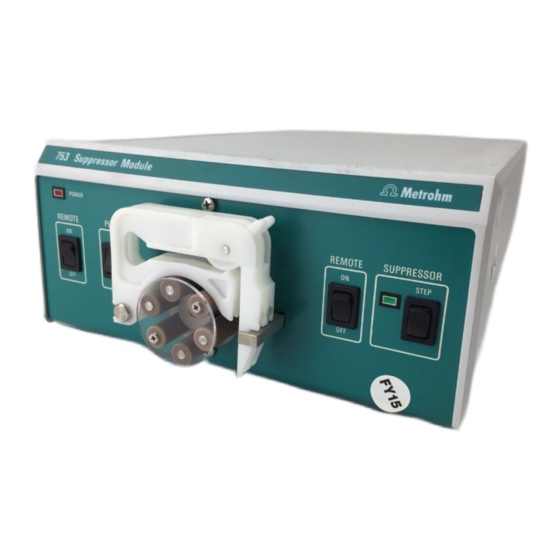
Metrohm POWER REMOTE PUMP REMOTE SUPPRESSOR STEP Fig. 1: Front of the 753 Suppressor Module Power on lamp Suppressor position display Lights up when instrument is Is lit up when the suppressor is "in switched on position" Pump Remote ON/OFF... -
Page 6: Fig. 2: Rear Of The 753 Suppressor Module
WARNING - Fire Hazard - For continued protection replace only Made by Metrohm Herisau Switzerland with the same type and rating of fuse Fig. 2: Rear of the 753 Suppressor Module Mains switch Connection for suppressor block For switching the instrument on/off:... -
Page 7: Information About The Instructions For Use
Information about the Instructions for Use Please read through these Instructions for Use carefully before you put the 753 Suppressor Module into operation. The Instructions for Use contain information and warnings to which the user must pay attention in order to assure safe operation of the instruments. -
Page 8: Notation And Pictograms
Caution This symbol marks important infor- mation. First read the associated directions before you continue. Comment This symbol marks additional in- formation and tips. 753 Suppressor Module / 8.753.1003 Instructions for Use... -
Page 9: Safety Notes
Safety notes 1.4.1 Electrical safety While electrical safety in the handling of the 753 Suppressor Module is assured in the context of the specifications IEC 1010-1 (protection class I, degree of protection IP20), the following points should be noted: • Mains connection... -
Page 10: Installation
2.1.4 Arrangement of the instruments The best position for the 753 Suppressor Module is beside the 690 Ion Chromatograph and below the 709 IC Pump. The 753 Suppressor Module should always be placed at the bottom... -
Page 11: Mains Connection
2.2.1 Setting the mains voltage Before switching on the 753 Suppressor Module for the first time, check that the mains voltage set on the instrument (see Fig. 2) matches the local mains voltage. If this is not the case, you must reset the mains... -
Page 12: Fuses
Module (see Fig. 4). 2.2.4 Switching the instrument on/off The 753 Suppressor Module is switched on and off using mains switch 13. When the instrument is switched on lamp 1 1 lights up. 753 Suppressor Module / 8.753.1003 Instructions for Use... -
Page 13: Connection To The 690 Ion Chromatograph
Module must be connected to the "Integrator Start" connection of the 690 Ion Chromatograph with the 6.2128.090 cable as shown in Fig. 5. Additionally switch 6 6 <REMOTE> on the front of the 753 Suppressor Module must be switched to "ON". -
Page 14: Fig. 6: Connections At Suppressor
Suppressor inlet capillary for H Detector Suppressor outlet capillary for H Suppressor outlet Waste capillary for H Suppressor inlet capillary for H Waste Suppressor outlet capillary for eluent Fig. 6: Connections at suppressor 753 Suppressor Module / 8.753.1003 Instructions for Use... - Page 15 10 10 and remove from mounting pin 12 12 on the 753 Suppressor Module (see Fig. 1). • Press contact pressure lever 5 5 on both tubing cartridges down as far as it will go. • Insert a length of pump tubing 33 33 (6.1826.050) into each of...
-
Page 16: Fig. 7: Installing Pump Tubings
32 on to the inlet end of the second pump tubing 33 33 (see Fig. 7). • Immerse the other end of the suction tubing in a vessel containing rinsing solution (normally dist. H O) and fix in place. 753 Suppressor Module / 8.753.1003 Instructions for Use... - Page 17 27 to a sufficiently large waste container and fix in place. 10 Startup of 753 Suppressor Module • Set switch <REMOTE> 2 2 on 753 Suppressor Module to "OFF". • Switch on 753 Suppressor Module with mains switch 13 13 and set switch <PUMP>...
-
Page 18: Connection To The 732/733 Ic System
"Remote" connection of the 732 IC Detector by means of the 6.2143.210 cable (available as an option) according to Fig. 8. Both switches 2 2 and 6 6 <REMOTE> on the front of the 753 Suppressor Module must additionally be set to "ON" to permit remote operation. - Page 19 22 22 to coupling 92 92 (6.2620.060) using a 6.2744.010 compression fitting. • Screw inlet capillary 78 78 of detector block 77 77 to the other end of the coupling 92 753 Suppressor Module / 8.753.1003 Instructions for Use...
- Page 20 10 10 and remove from mounting pin 12 12 on 753 Suppressor Module (see Fig. 1). • Press contact pressure lever 5 5 on both tubing cartridges down as far as it will go. • Insert a length of pump tubing 33 33 (6.1826.050) into each of...
- Page 21 12 Startup of 753 Suppressor Module • Set switch <REMOTE> 2 2 to "OFF". • Switch on 753 Suppressor Module with mains switch 13 13 and set switch <PUMP> 3 3 to "ON". • Adjust the contact pressure for both tubing cartridges: press contact pressure lever 5 5 upwards until the solutions just start to be drawn in.
-
Page 22: Operation
The suppressor must never be switched in the dry state as there is a danger of blocking. No recycling The recycling process (returning the eluent to the storage vessel) must not be carried out when the suppressor is in operation. 753 Suppressor Module / 8.753.1003 Instructions for Use... -
Page 23: Manual Operation
(mains connection, attaching the pump tubing, connection to the IC system). Switch instrument on/off The 753 Suppressor Module is switched on and off using mains switch 13 13 on the rear of the instrument (see Fig. 2): Instrument switched on... -
Page 24: Operation Via 690 Ion Chromatograph
Ion Chromatograph unless the installation has been carried out prop- erly as described in section 2 (mains connection, connection cable 690 – 753, attaching the pump tubing, connection to the IC system). When operating the 753 Suppressor Module together with the 690 Ion Chromatograph the pump on the suppressor module must still be switched on and off manually. -
Page 25: Operation Via 732 Ic Detector
Automatic pump switch-on when the 732 IC Detector is switched on In order to start up the pump drive of the 753 Suppressor Module automatically when the 732 IC Detector is switched on alterations must be made to the basic settings (Setup, see section 4.4.1 of 732/733 Manual). - Page 26 2 to 1 (on, active, 0 V). This lead must later be returned to the setting 0 (off, inactive, open) before the suppres- sor can be switched to the next position. 753 Suppressor Module / 8.753.1003 Instructions for Use...
- Page 27 TTTTTT Suppressor position display SUPPRESSOR The position display 7 7 of the 753 Suppressor Module beside switch 8 8 shows whether the suppressor is in the right position: STEP Lamp on Suppressor in the right position Lamp off Suppressor in the wrong position or blocked (procedure see section 4.1)
-
Page 28: Malfunctions - Maintenance
690 Ion Chromatograph (section 6.5) and 732/733 IC System (section 5.3.2). In addition to these general malfunctions the table below contains oth- ers which might arise as a result of the operation of the 753 Suppressor Module. Malfunction... - Page 29 (see below). • Suppressor dirty • Clean suppressor (see section 4.2.6). • Mechanical fault in suppressor • Exchange suppressor (see section 4.2.7). 753 Suppressor Module / 8.753.1003 Instructions for Use...
-
Page 30: Maintenance And Servicing
1.4.1. 4.2.2 Maintenance by Metrohm service Maintenance of the 753 Suppressor Module is best done as part of an annual service performed by specialists from the Metrohm company. If work is frequently performed with caustic and corrosive chemicals, it may be necessary to shorten the interval between servicing. -
Page 31: Exchanging The Pump Tubing
• Release tubing cartridge 4 4 from holding clamp 9 9 by pressing down snap-action lever 10 10 and remove from mounting pin 12 on the 753 Suppressor Module (see Fig. 1). • Remove old pump tubing. Insert new pump tubing •... -
Page 32: Regeneration Of The Suppressor
Connect suppressor to IC system • Reconnect suppressor to IC system. If there are still problems with the capacity then the suppressor rotor must be ex- changed (see section 4.2.6). 753 Suppressor Module / 8.753.1003 Instructions for Use... -
Page 33: Cleaning The Suppressor
4 mm inside the holder. If this is not the case then the rotor must be brought into the correct position from below with the aid of a sharp object (e.g. screwdriver). 753 Suppressor Module / 8.753.1003 Instructions for Use... -
Page 34: Fig. 9: Assembling The Suppressor
• Reconnect the suppressor to the IC system (see section 2.3.2 and section 2.4.2). • Before switching the suppressor to the next position for the first time rinse all 3 suppressor units with solution for 5 min. 753 Suppressor Module / 8.753.1003 Instructions for Use... -
Page 35: Exchanging The Suppressor
4 Malfunctions – Maintenance 4.2.7 Exchanging the suppressor Exchanging the suppressor in the suppressor block of the 753 Sup- pressor Module may be necessary in the following cases (see also section 4.1): • Loss of suppressor capacity which cannot be reme-... -
Page 36: Braking Range Adjustment
4.2.8 and readjust if necessary. 4.2.8 Braking range adjustment It may be necessary to readjust the braking range of the 753 Suppres- sor Module in the following cases (see also section 4.1): • Suppressor switches to next position but display lamp 7 7 no longer lights up •... -
Page 37: Fig. 10: Adjusting The Braking Range
Wait at least 10 s each time before operating key 8 8 <STEP>. unzulässig zulässig optimal zulässig unzulässig not acceptable acceptable optimum acceptable not acceptable Fig. 10: Adjusting the braking range 753 Suppressor Module / 8.753.1003 Instructions for Use... -
Page 38: Appendix
* A precondition for triggering a step is that the current flows for at least 10 ms. In order that a new step can be triggered no current must flow for at least 10 ms before. 753 Suppressor Module / 8.753.1003 Instructions for Use... - Page 39 Polyurethane rigid foam (PUR) with fire protection for fire class UL94VO, CFC-free Material of base Steel, enamelled Dimensions Width 260 mm Height 129 mm Depth 366 mm Weight 6.0 kg (incl. accessories) 753 Suppressor Module / 8.753.1003 Instructions for Use...
-
Page 40: Standard Equipment
5.2 Standard equipment Standard equipment Subject to changes! All dimensions are given in mm. The 2.753.0010 Suppressor Module includes the following parts: Quant. Order No. Description 1.753.0100 Suppressor block 6.1803.020 PTFE capillary tubing Length = 5 m 0.97 1.57 6.1826.050 Pump tubing ®... -
Page 41: Optional Accessories
5 Appendix Optional accessories Order No. Description 6.2143.210 Connecting cable Connecting cable 753 Suppressor Module – 732 IC Detector 6.2832.000 Suppressor rotor 6.2832.010 Connection piece to suppressor rotor with input and output leads 753 Suppressor Module / 8.753.1003 Instructions for Use... -
Page 42: Warranty And Conformity
Lack of an official damage report releases Metrohm from any liability to pay compensation. If any instruments and parts have to be returned, the original packaging should be used if at all possible. -
Page 43: Eu Declaration Of Conformity
5 Appendix 5.4.2 EU Declaration of conformity EU Declaration of Conformity The METROHM AG company, Herisau, Switzerland hereby certifies, that the in- strument: 753 Suppressor Module meets the requirements of EC Directives 89/336/EWG and 73/23/EWG. Source of the specifications: EN 50081-1... -
Page 44: Certificate Of Conformity And System Validation
International Certification Body (CB/IEC). The technical specifications are documented in the instruction manual. Metrohm Ltd. is holder of the SQS-certificate of the quality system ISO 9001 for quality assurance in design/development, production, installation and servicing. Herisau, November 8, 1996 Dr. - Page 45 5 Appendix 753 Suppressor Module / 8.753.1003 Instructions for Use...
-
Page 46: Index
IC Detector 732 ........22 Install tubing cartridges ....28 Opening the Suppressor Module...6 Immunity to interference...... 36 Control unit ..........1 Operation ..........19 Information about Correct connections ......19 Instructions for Use ......4 753 Suppressor Module / 8.753.1003 Instructions for Use... - Page 47 Figure ..........3 Startup........14,18 Technical data ......... 35 Switch 3 3 <PUMP> Remote interface 16 Figure ..........2 Figure ..........3 Function........20,21 Technical data ......... 35 Startup........14,18 Rinse column........11,16 753 Suppressor Module / 8.753.1003 Instructions for Use...
Need help?
Do you have a question about the 753 and is the answer not in the manual?
Questions and answers