Table of Contents
Advertisement
Quick Links
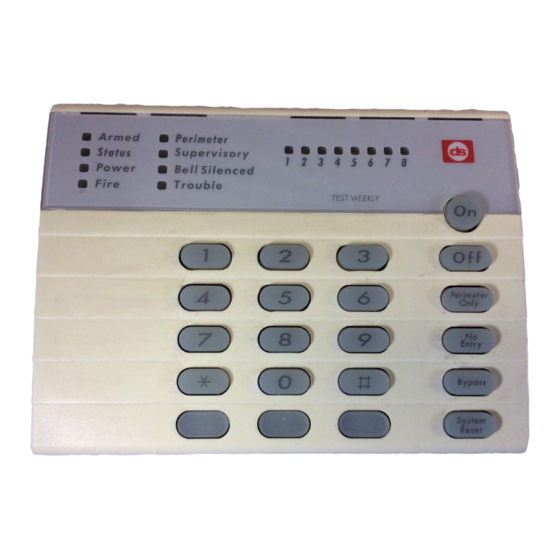
Armed
Status
Power
Fire
Normal Arming
Perimeter Arming, no entry delay
Perimeter Arming, with entry delay
Maximum Security Arming
Custom Arming
Force Arming
Set Delayed Arming
Delay Auto Arm by 15 Minutes
Zone Bypass
Change Partitions
Chime Mode
Zone Test
Event History Readback
Battery Test
Communicator Test
Fire Reset
Fire Trouble
Remote Program Dial-out
Remote Program Answer
Local Battery/Sounder Test
Error Display
Error Display Reset
Clear Zone Bypass
For additional information on system commands, see the DS7080iP-32 User's Guide P/N 39425
Downloaded from: http://www.guardianalarms.net
Reference Guide
DS7080iP-32 Two Partition
Control/Communicator
Ready To Arm
On
1
2
3
Perimeter
4
5
6
7
8
9
*
0
#
DS7447
Keypad Quick Reference Guide
Turning On (Arming) your System
Turning Off (Disarming) your System
Commands for other System Features
[Access Control PIN] + [Off]
for the
Armed
Perimeter
Status
Supervisory
Power
Bell Silenced
Fire
Trouble
Off
Only
No
Entry
Bypass
System
Reset
[PIN] + [On]
[PIN] + [No Entry] [Perimeter Only]
[PIN] + [Perimeter Only]
[PIN] + [No Entry] [On]
[PIN] + [#] [4]
[PIN] + [Arming Sequence] + [Bypass]
[PIN] + [#] [9] [9]
[PIN] + [OFF]
[PIN] + [Bypass] + [2-digit Zone number]
[PIN] + [#] [#]
[PIN] + [Off]
[PIN] + [#] [7]
[PIN] + [#] [8] [1]
[PIN] + [#] [8] [9]
[PIN] + [System Reset]
[PIN] + [#] [8] [2]
[PIN] + [System Reset]
[PIN] + [Off] to silence, [PIN] + [System Reset] to clear
[PIN] + [#] [8] [3]
[PIN] + [#] [8] [6]
[PIN] + [#] [8] [5]
[PIN] + [#] [8] [7]
[PIN] + [System Reset]
[PIN] + [Bypass] [*] to clear
Access Control
1 2 3 4 5 6 7 8
On
Off
1
2
3
Perimeter
4
5
6
7
8
9
*
0
#
DS7445
Only
No
Entry
Bypass
System
Reset
Advertisement
Table of Contents

Related Manuals for Detection Systems DS7080iP-32


Summary of Contents for Detection Systems DS7080iP-32
- Page 1 [PIN] + [#] [8] [7] Error Display Reset [PIN] + [System Reset] Clear Zone Bypass [PIN] + [Bypass] [*] to clear Access Control [Access Control PIN] + [Off] For additional information on system commands, see the DS7080iP-32 User’s Guide P/N 39425 Downloaded from: http://www.guardianalarms.net...
-
Page 2: Table Of Contents
7.11 Communicator Test ............22 Enclosure Housing ............. 4 7.12 Event History Readback ........... 22 Temperature ............... 4 8.0 How to Program the DS7080iP-32 ......23 Power ................. 4 9.0 Programming the DS7080iP-32 ......23 1.3.1 Accessory Power ............4 Address 001 - EX8 Zone Expansion Module Control .. - Page 3 9.49 Address 123 - Octal Relay Control and Reports ....40 9.50 Address 124 - Default Programming ......... 41 10.0 Installation Guide for UL Listed Systems ..... 42 10.1 DS7080iP-32 UL Listings: ..........42 10.2 Installation Considerations ..........42 10.2.1 Special Requirements for Partitioned Systems ..
-
Page 4: Specifications
Only one DS7443 is allowed per cable. Each DS7443 must • Storage and Operating Temperature: +32° to +120°F (0° to +49°C) have a “home run” back to the DS7080iP-32. Do not “daisy chain” or place two DS7443 keypads on any cable run. -
Page 5: Standby Current Load
100 mA Enclosure Installation Install the Control/Communicator The DS7080iP-32 control/communicator and the enclosure are The control is static sensitive. Make sure you touch shipped together. The control, however, still needs to be installed earth ground before handling the control. This will into the enclosure. -
Page 6: Control Terminal Wiring
“home run” or “daisy chained”. Maximum of 2 keypads a “home run”. Do not “daisy chain” keypads. per run for #22 AWG (.8mm) or 3 keypads for 18 AWG (1.0mm). Page 6 P/N 39818D Copyright © 2001 Detection Systems, Inc. DS7080iP-32 Reference Guide... -
Page 7: System Worksheet
System Worksheet DS7080iP-32 Reference Guide Copyright © 2001 Detection Systems, Inc. P/N 39818D Page 7... - Page 8 System Worksheet (continued) Page 8 P/N 39818D Copyright © 2001 Detection Systems, Inc. DS7080iP-32 Reference Guide...
-
Page 9: System Overview
• Fire Zone with Verification (B) • Zone: A zone is an input to the DS7080iP-32 Control/ • Fire Zone without verification (C) Communicator. There are 8 hard-wired zones on the main circuit •... -
Page 10: Glossary
Check local codes. - If this zone is violated after an entry/exit delay zone is violated, it will follow that entry/exit delay time. Page 10 P/N 39818D Copyright © 2001 Detection Systems, Inc. DS7080iP-32 Reference Guide... -
Page 11: Output Programming
Terminals 27 and 30 (one to Terminal 27, one to Users with authority to two partitions cannot custom arm a single Terminal 30) of the DS7080iP-32. partition. It appears in the history as level 4. - Not to be used in UL Listed systems. -
Page 12: Keypad Assignment Programming
Day Monitor zone is activated when the system is disarmed. The zone will cause an alarm when activated when the system is armed. Page 12 P/N 39818D Copyright © 2001 Detection Systems, Inc. DS7080iP-32 Reference Guide... -
Page 13: Phone Number General Control Programming
“B” emergency key. • Keypad Panic: This report is sent when an emergency alarm has been activated using the “C” emergency key. DS7080iP-32 Reference Guide Copyright © 2001 Detection Systems, Inc. P/N 39818D Page 13... -
Page 14: Event History Readback Control
Exit Error report will be sent. If the Exit Error report is enabled then the Bell Output will go on to warn the departing user. Page 14 P/N 39818D Copyright © 2001 Detection Systems, Inc. DS7080iP-32 Reference Guide... -
Page 15: Fcc Compliance Notice
This control should not be connected to party the requirement that the total of the Load Numbers of all the devices lines. does not exceed 100. The Load Number of the DS7080iP-32 is 2. Should this equipment cause harm to the telephone network, the RFI Requirements: telephone company may discontinue your service temporarily. -
Page 16: Operating Guide
If heavy smoke is present, drop to your hands and knees and crawl to remain below the smoke level. Page 16 P/N 39818D Copyright © 2001 Detection Systems, Inc. DS7080iP-32 Reference Guide... -
Page 17: Setting The Date
The control panel will exit from the Master Code Programming Mode approximately 15 seconds after the last keystroke. If the control panel loses power, the time will need to be set again. DS7080iP-32 Reference Guide Copyright © 2001 Detection Systems, Inc. P/N 39818D Page 17... -
Page 18: Personal Identification Numbers
[#] [7] or [#] [8] functions. any output programmed for Access Output (e.g. door strikes) will pulse on for 10 seconds (works when the system is armed or disarmed). Page 18 P/N 39818D Copyright © 2001 Detection Systems, Inc. DS7080iP-32 Reference Guide... -
Page 19: Automatic Arming
The keypad volume setting also applies to the Auto Arm tone. Note: The panel time and date must be set in order for this feature to work. DS7080iP-32 Reference Guide Copyright © 2001 Detection Systems, Inc. P/N 39818D Page 19... -
Page 20: Error Displays
* = If in “Residential Mode”, a PIN is not required for these commands. ** = Phone numbers 1 and 3 must be programmed. Phone #1 Account Code must be programmed. Page 20 P/N 39818D Copyright © 2001 Detection Systems, Inc. DS7080iP-32 Reference Guide... -
Page 21: Zone Test
• The control panel will report a Low Battery or a Low Battery Restoral * = If in “Residential Mode”, a PIN is not required for these commands. DS7080iP-32 Reference Guide Copyright © 2001 Detection Systems, Inc. P/N 39818D Page 21... -
Page 22: Communicator Test
To exit the Event History Mode, press the [*] key or wait 20 seconds and the keypad will exit automatically. Page 22 P/N 39818D Copyright © 2001 Detection Systems, Inc. DS7080iP-32 Reference Guide... -
Page 23: How To Program The Ds7080Ip-32
How to Program the DS7080iP-32 To enter the programming mode, the panel must be disarmed. When in the programming mode the control is disabled and no alarms will be processed, including 24-hour zones and fire zones. To enter the Programmer’s Mode, enter the [Programmer’s Code] followed by [#] [0]. Shorting the programming pads (see Section 2.2 for location) on the control panel will also activate the Programmer’s Mode. -
Page 24: Address 001 - Ex8 Zone Expansion Module Control
(except fire zones) will be sent during an armed period. • Force Arming Limit: Determines the maximum number of zones that may be force armed. Page 24 P/N 39818D Copyright © 2001 Detection Systems, Inc. DS7080iP-32 Reference Guide... -
Page 25: Address 003 - User Controls
Cross-zoning Trip Window Time programming defines the number of seconds for the Cross-zone Window. If 000 is used the trip window will be the duration of the arm cycle of the crossed non-24 hour zones. If they are 24 hour zones, then the duration is 24 hours. DS7080iP-32 Reference Guide Copyright © 2001 Detection Systems, Inc. P/N 39818D Page 25... -
Page 26: Address 007 - Keypad Assignment
Not available in Partitioned systems. Address 009 - Output Programming Output Programming is used to determine the output functions of the Alarm Output and Programmable Outputs 1 & 2. Page 26 P/N 39818D Copyright © 2001 Detection Systems, Inc. DS7080iP-32 Reference Guide... -
Page 27: Address 010 - Time Delays
Address 011 is used to determine report routing. Use options 0-3 for Non-partitioned systems. Do not select Options “4” through “C” “No Partitioning” is selected in Address 002 Digit 6. DS7080iP-32 Reference Guide Copyright © 2001 Detection Systems, Inc. P/N 39818D Page 27... -
Page 28: Address 012 - Phone Controls
4) If one of the Account Codes for Partition 2 or Parition 1 Phone #1 is programmed as 0000, then the panel will use the code programmed for Partition 1-Phone #1. 9.14 Address 014 - Partition 2 Account Codes See Note in Section 9.13. Page 28 P/N 39818D Copyright © 2001 Detection Systems, Inc. DS7080iP-32 Reference Guide... -
Page 29: Address 015 - Phone # 1 Format
9.15 Address 015 - Phone # 1 Format 9.16 Address 016 - Phone # 2 Format DS7080iP-32 Reference Guide Copyright © 2001 Detection Systems, Inc. P/N 39818D Page 29... -
Page 30: Address 017 - 022 - Phone Numbers
Dial Attempts be set to a value between 3 and 10. 9.19 Address 024 - Auto Test / Remote Programmer Call-Out Day Page 30 P/N 39818D Copyright © 2001 Detection Systems, Inc. DS7080iP-32 Reference Guide... -
Page 31: Address 025 - Auto Test / Remote Programmer Call-Out Time
Bypass Bypass 3 = Pulsing Audible PANIC KEY [C] System Reset System System Reset Reset A B C The Fire key is disabled if programmed as invisible. DS7080iP-32 Reference Guide Copyright © 2001 Detection Systems, Inc. P/N 39818D Page 31... -
Page 32: Addess 029 - Keypad Reports
Bypasses of these zones will be displayed on the keypad. Page 32 P/N 39818D Copyright © 2001 Detection Systems, Inc. DS7080iP-32 Reference Guide... - Page 33 Fire zones may not be manually bypassed or force bypassed. If force arming is enabled (see Programming Address 002), force arming is possible when the fire zone is violated (shorted). DS7080iP-32 Reference Guide Copyright © 2001 Detection Systems, Inc. P/N 39818D Page 33...
-
Page 34: Address 034, 035, 036, 037 - Zone Action
Bypassable in Address 042-045. The “Force Arm Limit”, set in Address 002, will be ignored when arming with keyswitches. Page 34 P/N 39818D Copyright © 2001 Detection Systems, Inc. DS7080iP-32 Reference Guide... -
Page 35: Address 042, 043, 044, 045 - Zone Bypass
1 = Partition 1 2 = Partition 2 3 = Partition 1 & 2 “Enable 2 Partitions” must be set in Address 002, digit 6, prior to Zone Partition Assignment. DS7080iP-32 Reference Guide Copyright © 2001 Detection Systems, Inc. P/N 39818D Page 35... -
Page 36: Addresses 054, 055, 056, 057 - Zone Alarm Reports
9.31 Addresses 054, 055, 056, 057 - Zone Alarm Reports Two Digits, 00 through FF 9.32 Addresses 058, 059, 060, 061 - Zone Restoral Reports Two Digits, 00 through FF Page 36 P/N 39818D Copyright © 2001 Detection Systems, Inc. DS7080iP-32 Reference Guide... -
Page 37: Addresses 062, 063, 064, 065 - Zone Trouble Reports
9.35 Addresses 070, 071, 072, 073 - Zone Bypass Reports Two Digits, 00 through FF 9.36 Addresses 074, 075, 076, 077 - Bypass Restoral Reports Two Digits, 00 through FF DS7080iP-32 Reference Guide Copyright © 2001 Detection Systems, Inc. P/N 39818D Page 37... -
Page 38: Address 078 - Open/Close Reports
9.39 Address 080 - Remote/Local Programming Reports 9.40 Address 081 - Exit Error, Recent Closing, System Trouble, System Trouble Restoral Reports 9.41 Address 082 - Test Reports Page 38 P/N 39818D Copyright © 2001 Detection Systems, Inc. DS7080iP-32 Reference Guide... -
Page 39: Address 083 - 116 - Alpha Labels
[#] Program the next address, program a different address or exit the Programmer’s Mode. 9.43 Address 117 - Point Expansion Module Missing Report 9.44 Address 118 - Point Expansion Module Missing Restoral Report DS7080iP-32 Reference Guide Copyright © 2001 Detection Systems, Inc. P/N 39818D Page 39... -
Page 40: Address 119 - Point Expansion Module Tamper Report
9.47 Address 121 - Point Expansion Module Fault Report 9.48 Address 122 - Point Expansion Module Fault Restoral Report 9.49 Address 123 - Octal Relay Control and Reports Page 40 P/N 39818D Copyright © 2001 Detection Systems, Inc. DS7080iP-32 Reference Guide... -
Page 41: Address 124 - Default Programming
Keypad programming (only the keypad set as Option Bus Address 1 will function), Alpha programming, Telephone numbers and Account codes. If the digit 1 is entered into Address 124 all programming information will be lost and cannot be recovered. DS7080iP-32 Reference Guide Copyright © 2001 Detection Systems, Inc. P/N 39818D Page 41... -
Page 42: Installation Guide For Ul Listed Systems
NFPA 72 for Household installations. This panel has not been investigated to the requirements of UL294 (Access Control). 10.1.1 The following table shows the DS7080iP-32 system configuration for the various types of fire and burglar alarm service for which the products are UL Listed. -
Page 43: Special Requirements For Partitioned Systems
• AC Failure Report (Program Address 079, digits 5 & 6) must be Required Accessories: programmed. • The control must be installed in a Detection Systems’ model B. Timer Programming: AE7080CC enclosure with a cover actuated tamper switch • Bell Cutoff Times (Program Address 010, digits 10-15) must be installed. -
Page 44: Police Station Connection
8 & 9 = 0. Required Accessories: • Program Address 008, digit 2, must be programmed for the • The control must be installed in a Detection Systems’ model Commercial mode (digit 2 = 0). AE7080CC enclosure with a cover actuated tamper switch 4. -
Page 45: Central Station Burglary Alarm
& 2) must be programmed. Required Accessories: • Close Report (Program Addresses 011, digit 1, and 078, digits 3 • The control must be installed in a Detection Systems’ model & 4) must be programmed. AE7080CC enclosure with a cover actuated tamper switch •... -
Page 46: Using The Ademco Ab-12 Bell/Housing
2) Connect wiring between the control and Bell Box as shown above. 3) Program Zone 8 as a 24-hour zone. (Program Address 030, digit 8, must be programmed as 2). Page 46 P/N 39818D Copyright © 2001 Detection Systems, Inc. DS7080iP-32 Reference Guide... -
Page 47: Report Programming Suggested Values
If sending reports to both a pager and to a central station, Do Not use a zero (0) as the reporting digit as it will disable the report to the central station. DS7080iP-32 Reference Guide Copyright © 2001 Detection Systems, Inc. P/N 39818D Page 47... - Page 48 Personal Dialing and Pager Format (suggested values) 4/2 Format (suggested values) Page 48 P/N 39818D Copyright © 2001 Detection Systems, Inc. DS7080iP-32 Reference Guide...
-
Page 49: Suggested Values For Bfsk And Other Pulse Formats
11.3 Suggested Values for BFSK and other Pulse Formats For Additional Information, see Programming Addresses 054-082 and 117-123. DS7080iP-32 Reference Guide Copyright © 2001 Detection Systems, Inc. P/N 39818D Page 49... -
Page 50: Report Programming Values Sent
Emergency Alarm Emergency Restore Tamper Alarm Tamper Restore Untyped Zone Alarm Untyped Zone Restore Untyped Zone Trouble Untyped Trouble Restore Power Supply Trouble Power Supply Restore Service Required Page 50 P/N 39818D Copyright © 2001 Detection Systems, Inc. DS7080iP-32 Reference Guide... -
Page 51: Contact Id Format Values Sent
12.2 Contact ID Format Values Sent For Additional Information, see Programming Addresses 054-082 and 117-123. DS7080iP-32 Reference Guide Copyright © 2001 Detection Systems, Inc. P/N 39818D Page 51... -
Page 52: High Speed 4/9 Format
12.3 High Speed 4/9 Format For Additional Information, see Programming Addresses 054-082 and 117-123. Page 52 P/N 39818D Copyright © 2001 Detection Systems, Inc. DS7080iP-32 Reference Guide... - Page 53 12.3 High Speed 4/9 Format (continued) DS7080iP-32 Reference Guide Copyright © 2001 Detection Systems, Inc. P/N 39818D Page 53...
-
Page 54: Programming Addresses
Zone Type Zones 17-24 ................032 Panic Key Report ..................029 Zone Type Zones 25-32 ................033 Partial Close Report ................078 Partition 1 Account Codes ..............013 Page 54 P/N 39818D Copyright © 2001 Detection Systems, Inc. DS7080iP-32 Reference Guide... -
Page 55: Troubleshooting Guide
= 6 - 7 Vdc devices are alarm on open, trouble on short. Trouble zone not activating. Not enabled or wired incorrectly. Check Program Address 003 . Check wiring. DS7080iP-32 Reference Guide Copyright © 2001 Detection Systems, Inc. P/N 39818D Page 55... - Page 56 # 87 Displays “Ram Fault” or “ROM Fault” reprogram. See Address 124. placement, bent, or mis-inserted pins. Do not touch while panel is 4. If error still persists, replace panel. powered up. Page 56 P/N 39818D Copyright © 2001 Detection Systems, Inc. DS7080iP-32 Reference Guide...
- Page 57 1. Day Monitor can send a trouble report if trouble report. desired. See Address 062-065 . 2. Zone programmed for trouble. 2. Check loop wiring. (see zone trouble) DS7080iP-32 Reference Guide Copyright © 2001 Detection Systems, Inc. P/N 39818D Page 57...
-
Page 58: Index
Interior Entry/Exit Follower 10, 33 Partition 1 Account Codes 28 Central Station Burglary Alarm 45 Interior Home/Away 10 Partition 2 Account Codes 28 Change Partitions 1 Interior Home/Away Zone 33 Page 58 P/N 39818D Copyright © 2001 Detection Systems, Inc. DS7080iP-32 Reference Guide... - Page 59 Local Programming Unsuccessful 38 Trouble Zone 9 Low Battery 14 Low Battery Restoral 14 Manual Comm. Test 14, 38 Octal Relay and Control 14 UL Listings 42 DS7080iP-32 Reference Guide Copyright © 2001 Detection Systems, Inc. P/N 39818D Page 59...
- Page 60 Detection Systems, Inc. 130 Perinton Parkway Copyright © 2001 Detection Systems, Inc. Fairport, New York, USA 14450-9199 DS7080iP-32 Reference Guide (585) 223-4060 • (888) 289-0096 • Fax: (585) 223-9180 P/N: 39818D 11/01 Page 60...
Need help?
Do you have a question about the DS7080iP-32 and is the answer not in the manual?
Questions and answers