Table of Contents
Advertisement
Advertisement
Table of Contents

Related Manuals for Detection Systems DS7443


Summary of Contents for Detection Systems DS7443
- Page 1 Using Your DS7060 Control/Communicator...
-
Page 2: Table Of Contents
Page 2 Contents Understanding the DS7443, DS7445, and DS7447 Keypads ............. 4 Personal Identification Numbers ....................6 Setting the Time ........................8 Setting the Date ........................9 Turning ON (arming) the System .................... 10 Quick Arming the System ....................... 12 Easy Exit .......................... - Page 3 Keypad Quick Reference Guide Turning On (arming) your System Turning Off (disarming) your System Normal Arming PIN + [On] PIN + [Off] Perimeter Arming, no entry delay PIN + [No Entry] [Perimeter Only] Perimeter Arming, with entry delay PIN + [Perimeter Only] Maximum Security Arming PIN + [No Entry] [On] Force Arming...
-
Page 4: Understanding The Ds7443, Ds7445, And Ds7447 Keypads
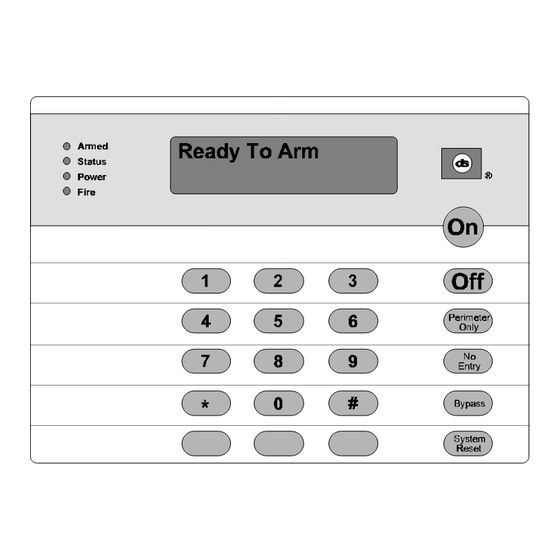
1.1 Understanding the DS7443, DS7445, and DS7447 Keypads The DS7443 is a 6 zone LED keypad; its LEDs represent the zones of the system. The DS7445 is an 8 zone LED keypad; its LEDs represent the zones of the system (LEDs for zones 7 and 8 are not used). - Page 5 This chart will help you understand what each light/LED represents. *= This light is present on the DS7445 only. **= This light is on the DS7443 and DS7445. Page 5...
-
Page 6: Personal Identification Numbers
The following chart will guide you through the steps necessary to add or change a PIN. It is recommended that this procedure be performed at a DS7447 keypad. No visual cues will be given from a DS7443 or DS7445 keypad. - Page 7 NOTE: Users 014 and 015 may be used for Duress and Guest Codes. See Sections 1.20 and 1.21. NOTE: You cannot read back User PIN numbers. You should keep a separate list for future reference. Removing a PIN To remove a PIN enter a [Master Code] [#] [0], the User Number of the PIN to be canceled, and then [#] again. User Number 001 can not be canceled.
-
Page 8: Setting The Time
Page 8 1.3 Setting the Time... -
Page 9: Setting The Date
1.4 Setting the Date Page 9... -
Page 10: Turning On (Arming) The System
Status light is off. If the green Status light is not on, or zone lights are displayed on the DS7443 or DS7445 keypad, or if the DS7447's display is reading “Not Ready,” then see Section 1.9 Force Arming or Section 1.11 Zone Bypass for other ways to arm the system. - Page 11 Page 11...
-
Page 12: Quick Arming The System
Page 12 1.6 Quick Arming the System If Quick Arming is not used, a PIN must be entered at the beginning of all arming command sequences. When Quick Arming is used, the following shortcuts are available. Ask your installation company if you desire this feature. 1.7 Easy Exit If the system is armed and there have been no zones violated, then you can reenter a Quick Arm Command without first disarming the system. - Page 13 WARNING: If the bells and sirens are on and/or the red Armed light is flashing, then the keypad is signaling that an alarm has occurred sometime before your arrival. The DS7447 will display “Zone Alarm.” The DS7443 or DS7445 zone LEDs will be flashing for the corresponding zone that is in alarm.
-
Page 14: Force Arming
Force Arming is required to arm the system. The DS7447 display will read “Not Ready” or “Fire Trouble” (if a fire zone is open) and the DS7443 and DS7445 zone LEDs (1-6) will be on if one of those zones is faulted. Ask your installation company if you desire this feature. -
Page 15: Auto Bypass
For instance, an open window may cause the DS7447 display to read "Not Ready" followed by the zone number. The DS7443 or DS7445 may have one of its zone LEDs on steady. - Page 16 Page 16 This chart explains the procedure for bypassing a faulted zone prior to arming the system. * If in “Residential Mode” substitute the [#] key for the PIN. NOTE: All bypasses are cleared when the system is disarmed, unless they are on 24-hour zones. To clear a bypass on a 24-hour zone, use Clear Individual or Clear All.
-
Page 17: Chime Mode
1.12 Chime Mode Chime Mode causes the keypad sounders to beep each time a Perimeter or Entry/Exit zone is violated while the control panel is off (disarmed). Only your installation company can determine which zones are chime zones. The [#] [7] command is used to both turn Chime Mode off and on. This chart explains the procedure for turning ON and turning OFF Chime Mode. - Page 18 Page 18 WARNING: Make sure that the report value programmed at these locations will be clearly understood at the Central Station. The “System in Test Report” will be sent, followed by the alarm and restoral reports of the zones being tested, providing their corresponding report address is programmed.
-
Page 19: Local Battery/Sounder Test
1.14 Local Battery/Sounder Test This test uses the battery to manually activate all the system sounders for two seconds. If the battery voltage is low, a battery fault will occur. Page 19... -
Page 20: Communicator Test
“Control Trouble Enter #87. When performing the #87 error display sequence, the DS7447 keypad will display “Control Trouble Communication Err”. The DS7443 and DS7445 keypads will turn on the Zone 3 LED. See Section 1.19 “Error Displays”. -
Page 21: Read Alarm History
1.16 Read Alarm History The history buffer stores the last 20 events in memory. The DS7447 can display all of these events. The DS7443/DS7445 can only display those zones (1-6) that have alarmed. **= If in Residential mode, a PIN is not required for this command. -
Page 22: Remote Program Dial-Out And Answer
A Fire Trouble will be indicated by a short beep from the keypad sounders every 10 seconds. The DS7447 will display “Fire Trouble” followed by the zones in a trouble condition. The DS7443 will turn the Fire light on steady and will light the corresponding zone LEDs. The DS7445 will turn the Fire and Trouble lights on steady and will light the corresponding zone LEDs. -
Page 23: Error Displays
Control panel problems are indicated by a flashing green Power light. The DS7447 display will also read “Control Trouble, Enter [#] [8] [7].” The DS7443 and DS7445 will only flash the green Power light. The error messages may only be read when the control is disarmed. Contact your installing company if the problems persist. - Page 24 The auxiliary power has been shorted. DS7447 - “Zone Trouble” DS7443 or DS7445 - LED of the zone in trouble will light One of the zones is not responding to the control panel. This may also be displayed during power-up (if so, ignore).
-
Page 25: Duress Code
1.20 Duress Code User Code 14 may be used as a duress PIN number. When the system is disarmed using this duress code, a silent report is sent to the central station. Duress codes are intended to be used when a user is forced to disarm the system. Ask your installation company if you desire this feature. -
Page 26: Emergency Keypad Alarms
Caution When Entering A Building If the bells and sirens are on and/or the red Armed light is flashing (with the DS7447 display reading “Zone Alarm” or the DS7443 or DS7445 having its zone LEDs flashing) then the keypad is signaling that an alarm has occurred. The keypad will also issue a pulsed tone during the entry delay instead of the usual steady tone. -
Page 27: Fire Safety
The Emergency Alarm Keys [A], [B], and [C] may generate Fire, Special Emergency, and Panic Alarms if programmed by the installer. Ask your installing company to explain the function of these keys. When using the Emergency Alarm Keys, they must be pressed for two seconds to generate an alarm. NOTE: If the Emergency Alarm keys are to be used, they should be labeled to signify their functions. - Page 28 Page 28 Having and Practicing an Escape Plan A fire warning may be wasted unless the family has planned in advance for a rapid and safe exit from the building. • Draw a floor plan of the entire house showing two exits from each bedroom and two from the house. Since stairwells and hallways may be blocked during a fire, the plan should provide exits from bedroom windows.
- Page 29 • Do not install smoke detectors where normal area temperatures are above 100° F (38° C) or below 32° F (0° C). • Areas of high humidity and dust concentrations should be avoided. The edge of ceiling mounted detectors should be no closer than 4 inches (10 cm) from any wall. •...
- Page 30 Page 30...
- Page 31 Page 31...
-
Page 32: Index
Test 17 Trouble 22 Guest Code 25 Keypads Backlight Control 4 DS7443 4 DS7445 4 DS7447 4 Volume Control 4 Copyright © 1996-98 Detection Systems, Inc., 130 Perinton Parkway, Fairport, New York, USA 14450-9199 DS7060 Users Guide P/N 29955E 11/98...
Need help?
Do you have a question about the DS7443 and is the answer not in the manual?
Questions and answers