Detection Systems DS7445 User Manual
Ds7400xi (version 3+) security system
Hide thumbs
Also See for DS7445:
- Reference manual (60 pages) ,
- User manual (48 pages) ,
- Quick reference manual (32 pages)
Table of Contents
Advertisement
Quick Links
Download this manual
See also:
Quick Reference Manual
DS7400Xi (version 3+) Security System
when used with a DS7447/DS7447E or DS7445/DS7445i keypad
Armed
Perimeter
Status
Supervisory
1 2 3 4 5 6 7 8
Power
Bell Silenced
Trouble
9 10 11 12 13 14 15 16
Fire
TEST WEEKLY
1
2
4
5
7
8
*
0
DS7445/DS7445i
LED Keypad
User's Guide
An instruction guide for your alarm system
On
Off
3
Perimeter
6
Only
No
9
Entry
#
Bypass
System
Reset
Armed
Status
Power
Fire
TEST WEEKLY
1
2
4
5
7
8
*
0
DS7447/DS7447E
Alpha "English Display" Keypad
On
Off
3
Perimeter
6
Only
No
9
Entry
#
Bypass
System
Reset
Advertisement
Table of Contents

Related Manuals for Detection Systems DS7445


Summary of Contents for Detection Systems DS7445
-
Page 1: Led Keypad
DS7400Xi (version 3+) Security System User’s Guide An instruction guide for your alarm system when used with a DS7447/DS7447E or DS7445/DS7445i keypad Armed Armed Perimeter Status Supervisory Status 1 2 3 4 5 6 7 8 Power Bell Silenced Power... -
Page 2: System Overview
System Overview Congratulations on the installation of your new security system. No other investment can provide such peace of mind. Welcome to the DS7400Xi intrusion/fire control system. Since each installation is unique, yours will contain some, but not necessarily all of the features mentioned in this guide. -
Page 3: Table Of Contents
Important ................3 Error Displays ..............30 Day to Day Operations ............4 System Faults ..............31 Understanding the DS7447/DS7447E and DS7445/ Testing your System ............32 DS7445i Keypads ............. 4 Zone Test................32 Turning ON (arming) your System ........6 Battery Test. -
Page 4: Day To Day Operations
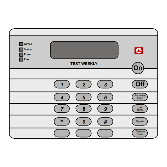
9 10 11 12 13 14 15 16 Fire Fire TEST WEEKLY The DS7447/DS7447E is an alpha-numeric LCD keypad. TEST WEEKLY The DS7445/DS7445i is an LED keypad; its LEDs 1-8 repre- sent the first 8 zones of the system. Perimeter Perimeter Only Only... - Page 5 Understanding the DS7447/DS7447E and DS7445/DS7445i Keypads (continued) These Lights Present on the DS7445/DS7445E Only: Light Flashing Perimeter Panel is disarmed or This Light will not flash. The perimeter is armed. (yellow) is not armed Perimeter. Supervisory There are no supervisory A supervisory condition exists.
-
Page 6: Turning On (Arming) Your System
In commercial burglar alarm applications for U.L. Listed systems, a ring-back indication and bell test should be heard after arming (closing). If not heard, call for service. * = DS7447/DS7447E only ** = DS7445/DS7445i only - 6 - continued on next page... - Page 7 Note: In commercial burglar alarm applications for U.L. Listed systems, a ring-back indication * = DS7447/DS7447E only and bell test should be heard after arming (closing). If not heard, call for service. ** = DS7445/DS7445i only - 7 -...
-
Page 8: Quick Arming Your System
Quick Arming your System This chart explains four ways to quick arm the system from a Standard keypad. If Quick Arming is not used, a PIN must be entered at the beginning of all arming command sequences. When Quick Arming is used, the following short-cuts are available: Quick Arming Command Sequence Type of Arming [#] + [On]... -
Page 9: Turning Off (Disarming) Your System / Silencing Alarms
When silencing a fire alarm, the DS7447/DS7447E will display “ Sounder Silencing Alarms [PIN] + [Off] Silenced ” and the DS7445/DS7445i will light the Bell Silenced LED until the system has been reset. When in Commercial Fire Mode, entering your [PIN] followed by the [#] key a second time - 9 - allows you to locate the fire zone number(s) that is (are) in alarm. -
Page 10: Force Arming Your System
DS7447/DS7447E display will read “Not Ready” and the (close doors and windows, etc.) before using these features. If DS7445/DS7445i's zone LEDs (1-8) will be on when Force Arming the problem can not be corrected, contact your installing is required to arm the system. -
Page 11: Zone Bypass
Bypass commands only work when the control panel is disarmed. For instance, an open window may cause the DS7447/ DS7447E display to read “Not Ready” followed by the zone number. The DS7445/DS7445i may have one of its zone 1-16 LEDs on steady. -
Page 12: Automatic Arming
Automatic Arming Each partition can be programmed to automatically arm once per day. To program the Automatic Arming time, perform the following: Setting the Automatic Arming Time Notes Setting the Automatic Arming Time can only be performed in the Master Enter a [Master PIN] + [#] + [0] Programming Mode. -
Page 13: Automatic Disarming
Automatic Disarming Each partition can be programmed to automatically disarm once per day. To program the Automatic Disarming time, perform the following: Notes Setting the Automatic Disarming Time Setting the Automatic Disarming Time can only be performed in the Master Enter a [Master PIN] + [#] + [0] Programming Mode. -
Page 14: Delaying Automatic Arming
Delaying Automatic Arming This section explains how to delay the Automatic Arming Time. To inform occupants that the system is about to arm, a pre-arming period will begin 15 minutes before the system arms auto- matically. The keypad sounders, and any outputs programmed to follow the keypad sounders, will pulse five times every minute. During the last five minutes before arming, these sounders will be on steady. -
Page 15: Delayed Arming
Delayed Arming This section explains how to cause the system to arm after a specified number of hours. Delayed arming is simply causing the system to arm after a specified number of hours. To program the system for delayed arming, perform the following steps: Delaying Arming Notes Enter a [PIN]... -
Page 16: Chime Mode
Chime Mode This chart explains the procedure for turning ON and turning OFF Chime Mode. Chime Mode causes the keypad sounders to beep each time a Perimeter or Entry/Exit zone is violated while the control panel is off (disarmed). The [#] [7] command is used to turn Chime Mode both off and on. This will only activate or de-activate the keypad(s) in the partition you are entering from. -
Page 17: Access Control
Access Control This chart explains the procedure for activating devices that require an Access Control PIN. Your system may use a keypad key sequence to activate other electrical devices. The special PIN required to perform this function is known as an Access Control PIN. This feature can be used in armed or disarmed modes. -
Page 18: Changing The Date
If a delay of 15 seconds or more occurs between your entries, the 3-beep error tone occurs and exits you from the programming mode. It is recommended that this procedure be performed at a DS7447/DS7447E keypad. No visual clues will be given from a DS7445/ DS7445i keypad. -
Page 19: Changing The Expiration Date (For Temporary Pins)
If a delay of 15 seconds or more occurs between your entries, the 3-beep error tone occurs and exits you from the programming mode. It is recommended that this procedure be performed at a DS7447/DS7447E keypad. No visual clues will be given from a DS7445/DS7445i keypad. Steps to Change the Date Command Sequence... -
Page 20: Changing The Time
If a delay of 15 seconds or more occurs between your entries, the 3-beep error tone occurs and exits you from the programming mode. It is recommended that this procedure be performed at a DS7447/DS7447E keypad. No visual clues will be given from a DS7445/DS7445i keypad. Steps to Change the Date Command Sequence... -
Page 21: Emergency Procedures
“Zone Alarm” you are confronted with an actual emergency. • The DS7445/DS7445i zone LEDs 1-8 are flashing. The keypad will also issue a pulsed tone during the entry delay Silencing Alarms instead of the usual steady tone. -
Page 22: Turning Off (Disarming) Your System Under Duress
Turning OFF (disarming) your System under Duress This chart explains the proper procedure for disarming under Duress. Ask your installer if the Duress feature has been activated. A Duress code is used when someone demands, by threatening your life or well-being, that the system be turned off. When used, the code will both turn off the system and report a silent Duress alarm if connected to a monitoring service. -
Page 23: Emergency Keypad Alarms / Silencing Alarms
Emergency Keypad Alarms / Silencing Alarms Armed Armed Perimeter Status Status Supervisory 1 2 3 4 5 6 Power Bell Silenced Power Fire Trouble 9 10 11 12 13 14 15 16 Fire TEST WEEKLY Perimeter Perimeter Only Only Entry Entry Bypass Bypass... -
Page 24: Fire Reset / Fire Trouble
“Fire Trouble” followed by the zones in a trouble condition. The which smoke detector has alarmed so the monitoring DS7445/DS7445i will turn the Fire and Trouble Lights on steady company may verify its operation. and will light the corresponding zone LEDs. -
Page 25: Fire Safety
Fire Safety WARNING: No fire detection device or system should be considered 100 percent foolproof. This fire alarm system can provide early warning of a developing For added early warning protection, it is recommended that fire. Such a system, however, does not ensure protection against detectors be installed in all separated areas including the property damage or loss of life resulting from a fire. -
Page 26: Installation Considerations
Fire Safety (continued) • Provide a barricade between family members and fire, smoke Installation Considerations and toxic gases (i.e. close all bedroom doors before retiring). Proper location of detection devices is one of the most critical • Children should be instructed on opening their bedroom win- factors in a fire alarm system. -
Page 27: Personal Identification Numbers
Personal Identification Numbers General Information User Number 001 is designated as a Master code. It can be used to add, delete, or change other PINs. It will always have When programming Personal Identification Numbers, it is help- access to all partitions regardless of how it is programmed. ful to know the following terms: User Number 001 is shipped from the factory with the PIN of 1 2 3 4. -
Page 28: Change A Pin
If a delay of 15 seconds or more occurs between your entries, the 3-beep error tone occurs and exits you from the programming mode. It is recommended that this procedure be performed at a DS7447/DS7447E keypad. No visual clues will be given from a DS7445/DS7445i keypad. Command Sequence If Accepted, DS7447/DS7447E Display... -
Page 29: Pin Authority Levels
Personal Identification Numbers (continued) PIN Authority Levels 4 = Temporary: Valid only for a specified time (the PIN will disappear upon 0 = Master: expiration date). It can arm and disarm the system, but can Can enter all commands, add or change PINs in assigned not perform any other functions. -
Page 30: Error Displays
To Clear a display, enter [PIN] + [System Reset]. or if you are certain the problem has been remedied. Error Message Meaning DS7447/ DS7445/ DS7447E DS7445i Power Light Control Trouble There is an Error Message. To display the message, enter [PIN] + [#][8][7]. -
Page 31: System Faults
System Faults System Faults are designated as follows: System faults are designated as follows: [#] [8] [9] will display [#] [8] [7] will display RAM Fault System fault 01 ROM Fault System fault 02 EEPROM Fault System fault 03 Ground Fault System fault 04 2Ph/Bell Fault = loss of communication to DS7420i System fault 10... -
Page 32: Testing Your System
DS7447/DS7447E followed by the zone number of any zones that have not been tested. Test each detector The DS7445/DS7445i will flash the one at a time as zone LEDs of any untested zones. instructed by the “ Now Testing ” will display on the installing company. -
Page 33: Battery Test
Testing your System (continued) This chart explains the procedure for performing a Battery Test. If a power failure occurs, your control panel has a built-in battery that will continue to power the control panel for many hours. The control panel automatically recharges the battery when power is restored. In addition to an automatic battery test performed every 2 minutes, the battery may also be tested manually. -
Page 34: Communicator Test
Testing your System (continued) This chart explains the procedure for performing a Communicator Test. This test is available only if your system transmits alarms and system information to a monitoring service, and has been programmed by the security installing company to permit communicator tests. This test can be performed from a Master Keypad. -
Page 35: Fire Walktest
DS7447/DS7447E: “Fire Test” will display followed by the zone number of any zones that have not been tested. DS7445/DS7445i: The Zone LEDs will flash for any zones that have not Test each detector one at a time as been tested. ** instructed by the installing company. -
Page 36: Event History Readback
This chart explains the procedure for performing an Event History Readback. The History Buffer stores the last 400 events in memory. The DS7447/DS7447E can display all of these events. The DS7445/ DS7445i will only display those zones (1-8) that have alarmed since the last Event History Readback. -
Page 37: The Master Keypad General Information
The Master Keypad - DS7447/DS7447E only Your system may include a Master keypad. A Master keypad is a DS7447/DS7447E keypad programmed to give a user access to all the partitions he has access to, not just the partition the Master keypad is in. This is different from a Standard keypad in that Standard keypads only give access to the single partition they are in. -
Page 38: Master Keypad Displays
Master Keypad Displays - DS7447/DS7447E only This chart will help you understand what each Light function of the Master keypad represents. Light Flashing One or more partitions Armed All partitions are armed, and no alarms have All partitions are disarmed. are armed, or an alarm (red) occurred. -
Page 39: Arming From The Master Keypad
Arming from the Master Keypad - DS7447/DS7447E only This chart will help you to Arm from the Master keypad. Arming from the Master keypad Arming all the Enter your PIN followed by one of the arming sequences. Partitions you have This will arm all of your partitions, even if some are already armed. -
Page 40: Disarming From The Master Keypad
Disarming from the Master Keypad - DS7447/DS7447E only This chart will help you to Disarm from the Master keypad. Disarming from the Master keypad Disarming all the Enter your PIN followed by the [Off] key. Partitions you have This will disarm all of your partitions, even if some are already disarmed. access to You must enter Single Partition Mode to disarm the necessary partitions one at a time (see page 39). -
Page 41: Single Partition Mode
Single Partition Mode - DS7447/DS7447E only Single Partition Mode is used to control partitions on a “one at a time/one by one” basis from the Master keypad. To enter the Single Partition Mode, enter your [PIN], then press the [#] key twice. This will call up the first partition you have access to. -
Page 42: Glossary
Glossary Access Control PIN common entry way to separate Entry Delay An Access Control PIN is a special partitions. A Master keypad would An Entry Delay is a predetermined code used to activate electric door normally be found in the Common Area. amount of time that allows entry into locks or other mechanisms connected A Common Area is only armed when... - Page 43 Glossary (continued) Installing Company Partitioning The Installing Company is the company Partitioning divides the system into 2, that physically installed the system. It 3, 4, 5, 6, 7, or 8 areas or partitions. may or may not be the same company This allows the system to act as 2, 3, who monitors the system.
-
Page 44: Index
Date, Changing the ......18 Keypads ......2, 4, 5, 23 Trouble Light ........5 Disarming ....9, 13, 22, 40, 42 DS7445/DS7445i Display ....4, 5 LEDs 1-8 ..........5 Zone ..........43 DS7447/DS7447E Display ..... 4, 5 Local System ........43 Zone Bypassing ...... -
Page 45: Quick Reference Guide
Quick Reference Guide Maintenance and Service The system should be tested weekly to ensure it is functioning properly. If problems are detected in testing or changes are noticed in normal operation, call your installing company for service. The manufacturer recommends replacing the system battery every 3 to 5 years. - Page 46 Quick Reference Guide (continued) Zone Protection Zone Protection Zone Protection Zone Protection Zone Protection 65 _______________ 78 _______________ 91 _______________ 104_______________ 117 _______________ 66 _______________ 79 _______________ 92 _______________ 105_______________ 118 _______________ 67 _______________ 80 _______________ 93 _______________ 106_______________ 119 _______________ 68 _______________ 81 _______________ 94 _______________...
-
Page 47: System Features Reference Guide
System Features Reference Guide Audible Alarm Signalling Device Sounds Force Arming Intrusion ( ) Pulse ( ) Continuous Enter an arming command sequence followed by the [Bypass] Fire ( ) Pulse ( ) Continuous key. The maximum number of zones that can be forced armed is _____ Keypad Supplemental Alarm [B] Key ( ) Continuous... - Page 48 32781F P/N: Guide User’s (Ver. DS7400Xi 14450-9199 York, Fairport, Inc. Systems, Detection 2004 © Copyright Parkway Perinton Inc., Systems, Detection 12/04 numberr above Company Installing your contact Please [Off]. followed PIN] Code [Access your Enter Control Access [PIN] Test Walk Fire [PIN] Readback...
Need help?
Do you have a question about the DS7445 and is the answer not in the manual?
Questions and answers