Table of Contents
Advertisement
Quick Links
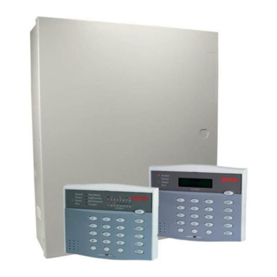
for the DS7400Xi-AT (Version 3+)
Turning On (arming) your System using the DS7445 or
DS7447 Keypad
Normal Arming
Perimeter Arming, no entry delay
Perimeter Arming, with entry delay [PIN] + [Perimeter Only]
Maximum Security Arming
Custom Arming
Set Delayed Arming
Extend Automatic Arming
during pre-arm time
Force Arming
Zone Bypass
Turning Off (disarming) your System
Enter your [PIN] followed by [Off]
Detection Systems, Inc. 130 Perinton Parkway
Fairport, New York, USA 14450-9199
(716) 223-4060 • (800) 289-0096 • Fax: (716) 223-9180
Reference Guide
Control/Communicator
Keypad Quick Reference Guide
[PIN] + [On]
[PIN] + [No Entry] +
[Perimeter Only]
[PIN] + [No Entry] + [On]
[PIN] + [#] [4]
[PIN] + [#] [9] [9] and enter
number of hours from current
time to the desired arming time.
[PIN] + [OFF]
Enter an arming command
followed by [Bypass]
[PIN] + [Bypass] followed by
the Zone number.
[PIN] +[Bypass] + [*] to clear
ALL Bypasses.
Commands for other System Features
Chime Mode
System Walk Test
Event History Readback
Battery Test
Communicator Test
Fire Reset
Remote Program Dial-out
Remote Program Answer
Battery/Sounder Test
Error Display
Clear Error Display
Fire Walk Test
Smoke Detector Test
To Silence a Fire Trouble/Alarm
To Clear a Fire Trouble Display
Access Control
Enter your [Access Control PIN] followed by [Off]
Copyright © 1995-2000 Detection Systems, Inc.
DS7400Xi-AT Reference Guide P/N: 39766B
[PIN] + [#] [7]
[PIN] + [#] [8] [1]
[PIN] + [#] [8] [9]
[PIN] + [System Reset]
[PIN] + [#] [8] [2]
[PIN] + [System Reset]
[PIN] + [#][8] [3]
[PIN] + [#] [8] [6]
[PIN] + [#] [8] [5]
[PIN] + [#] [8] [7]
[PIN] + [System Reset]
[PIN] + [#] [9] [1]
[PIN] + [#] [9] [2]
[PIN] + [Off]
[PIN] + [System Reset]
February, 2000
Advertisement
Table of Contents

Related Manuals for Detection Systems DS7400Xi-AT

Summary of Contents for Detection Systems DS7400Xi-AT
- Page 1 Reference Guide for the DS7400Xi-AT (Version 3+) Control/Communicator Keypad Quick Reference Guide Turning On (arming) your System using the DS7445 or Commands for other System Features DS7447 Keypad Chime Mode [PIN] + [#] [7] Normal Arming [PIN] + [On] System Walk Test...
- Page 2 Program Address (0166) ........40 Changing the Date ..........23 11.6 Zone Bypass Programming: Changing the Temporary PIN Expiration Date ..23 Program Addresses (0016-0017) ....... 41 DS7400Xi-AT (Ver. 3+) Reference Guide Copyright © 1995-2000 Detection Systems, Inc. Page 2...
-
Page 3: Table Of Contents
11.34 Octal Relay Module Output Programming: 18.0 Program Addresses ..........89 Program Addresses (1456-1471) ....... 58 Index ................. 92 11.34.1 Octal Relay Module Output Partition Assignment: Program Addresses (3725-3732) ..........59 DS7400Xi-AT (Ver. 3+) Reference Guide Copyright © 1995-2000 Detection Systems, Inc. Page 3... - Page 4 1.14 Option Bus Wiring Requirements • Maximum wire length 1000 feet (305 m) per home-run. DS7400Xi-AT (Ver. 3+) Reference Guide Copyright © 1995-2000 Detection Systems, Inc. Page 4...
- Page 5 • Battery AH - (20% Storage + 0.375 AH’s Alarm) • The following table is the derated battery divided by hours minus the control standby (175 mA): DS7400Xi-AT (Ver. 3+) Reference Guide Copyright © 1995-2000 Detection Systems, Inc. Page 5...
- Page 6 • Current Draw = 100 mA, Standby. 100 mA, Alarm. • Keypad Access Output: The DS7447 Alpha Key pad will provide a ten (10) second access relay DS7400Xi-AT (Ver. 3+) Reference Guide Copyright © 1995-2000 Detection Systems, Inc. Page 6...
- Page 7 DS7430 and occupies one multiplex zone. • Current Draw= 200 µA standby, 2.5 mA in smoke and automatically determines the detector’s sensitivity using the Detection Systems “Chamber walk test mode. Check” feature. The MX280 Detector has not been • MX950: TriTech®...
- Page 8 • Pre-start the mounting screws for these two holes. Slide the enclosure onto these mounting screws so that the screws move up into the thinner section of the holes. Tighten the screws. DS7400Xi-AT (Ver. 3+) Reference Guide Copyright © 1995-2000 Detection Systems, Inc. Page 8...
- Page 9 Control Terminal Wiring DS7400Xi-AT (Ver. 3+) Reference Guide Copyright © 1995-2000 Detection Systems, Inc. Page 9...
- Page 10 • A Communications Module may be connected to the control panel via the Options Bus. This allows for connection to the ARDIS radio network. • Up to 128 zones are available for the connection of Single, Multiple, Input/Output, and Multiplex devices. DS7400Xi-AT (Ver. 3+) Reference Guide Copyright © 1995-2000 Detection Systems, Inc. Page 10...
- Page 11 System Worksheet DS7400Xi-AT (Ver. 3+) Reference Guide Copyright © 1995-2000 Detection Systems, Inc. Page 11...
- Page 12 System Worksheet (continued) DS7400Xi-AT (Ver. 3+) Reference Guide Copyright © 1995-2000 Detection Systems, Inc. Page 12...
- Page 13 System Worksheet (continued) DS7400Xi-AT (Ver. 3+) Reference Guide Copyright © 1995-2000 Detection Systems, Inc. Page 13...
- Page 14 System Worksheet (continued) DS7400Xi-AT (Ver. 3+) Reference Guide Copyright © 1995-2000 Detection Systems, Inc. Page 14...
- Page 15 - If the system is not disarmed during the entry period, this zone will activate an alarm. DS7400Xi-AT (Ver. 3+) Reference Guide Copyright © 1995-2000 Detection Systems, Inc. Page 15...
- Page 16 - If this zone is programmed for trouble on open and the loop opens, the DS7447 keypad will display “Fire Trouble” and “Control Trouble” and the keypad sounders will beep once every ten seconds. DS7400Xi-AT (Ver. 3+) Reference Guide Copyright © 1995-2000 Detection Systems, Inc. Page 16...
- Page 17 Output Functions as described above. zone is in an alarm condition. - It will remain activated until the system is disarmed or the bell cut-off time expires. DS7400Xi-AT (Ver. 3+) Reference Guide Copyright © 1995-2000 Detection Systems, Inc. Page 17...
- Page 18 2 seconds. delay, do not program the control panel unit to exceed 120 - It may be programmed for a steady or pulsed alarm. seconds combined time delay. DS7400Xi-AT (Ver. 3+) Reference Guide Copyright © 1995-2000 Detection Systems, Inc. Page 18...
- Page 19 • Keypad Panic: This report is sent when an emergency alarm • Low Battery: This report is sent when a low battery condition has been activated using the “C” emergency key. occurs. DS7400Xi-AT (Ver. 3+) Reference Guide Copyright © 1995-2000 Detection Systems, Inc. Page 19...
- Page 20 • System Walk Test Restoral: This report is sent when the system the interference by one or more of the following measures: test has been completed or has timed-out. DS7400Xi-AT (Ver. 3+) Reference Guide Copyright © 1995-2000 Detection Systems, Inc. Page 20...
- Page 21 (telephone extension cord). The customer should be aware that compliance with the above conditions may not prevent degradation of service in some situations. DS7400Xi-AT (Ver. 3+) Reference Guide Copyright © 1995-2000 Detection Systems, Inc. Page 21...
- Page 22 Access Output (e.g. door strikes) will pulse on for 10 seconds (works when the system is armed or disarmed). You must program a Temporary PIN expiration date before programming Temporary PINs. DS7400Xi-AT (Ver. 3+) Reference Guide Copyright © 1995-2000 Detection Systems, Inc. Page 22...
- Page 23 For commands to Arm, Disarm, Bypass or set chime mode, see the front cover of this Reference Guide or consult the DS7400Xi Ver. 3+ Users Guide. Changing the Date Changing the Temporary PIN Expiration Date DS7400Xi-AT (Ver. 3+) Reference Guide Copyright © 1995-2000 Detection Systems, Inc. Page 23...
- Page 24 Delayed arming will override automatic arming. Delayed arming will also provide a 15 minute pre-arm period like the one provided with automatic arming. DS7400Xi-AT (Ver. 3+) Reference Guide Copyright © 1995-2000 Detection Systems, Inc. Page 24...
- Page 25 [PIN] + [OFF]. For a longer delay, perform the following steps: To extend the Automatic Arming at any time, use the Delayed Arming feature (see section 7.6). DS7400Xi-AT (Ver. 3+) Reference Guide Copyright © 1995-2000 Detection Systems, Inc. Page 25...
- Page 26 If automatic disarming is used in Master Keypad mode, it will affect all partitions you have access to. If used in single partition mode, or from a single partition keypad, it will affect only the partition you are working in. To program the Automatic Disarming Time, perform the following steps: DS7400Xi-AT (Ver. 3+) Reference Guide Copyright © 1995-2000 Detection Systems, Inc. Page 26...
- Page 27 See the “Fire Reset” section, 7.11.1. The Dirty Chamber beep can be silenced with any [PIN] + the [Off] key. Notify your installing company immediately if the Dirty Chamber message is displayed. DS7400Xi-AT (Ver. 3+) Reference Guide Copyright © 1995-2000 Detection Systems, Inc. Page 27...
- Page 28 • Draw a floor plan of the entire house showing two exits from smoke level. each bedroom and two from the house. Since stairwells and hallways may be blocked during a fire, the plan should provide DS7400Xi-AT (Ver. 3+) Reference Guide Copyright © 1995-2000 Detection Systems, Inc. Page 28...
- Page 29 When a fire zone is tested, any output programmed to follow that zone will activate for 5 seconds. A Fire Walk Test will prevent the system from sending any Fire Reports during the test. DS7400Xi-AT (Ver. 3+) Reference Guide Copyright © 1995-2000 Detection Systems, Inc. Page 29...
- Page 30 MX280 Series Smoke Detectors. It will prevent the system from cannot be used to check standard sending any Fire Reports during 2- or 4-wire smoke detectors. the test. DS7400Xi-AT (Ver. 3+) Reference Guide Copyright © 1995-2000 Detection Systems, Inc. Page 30...
- Page 31 To exit the Event History Mode, press the [*] key or wait 20 seconds and the keypad will exit automatically. When performing this from a Master Keypad, each partition will display its own history. 7.14.7 Remote Program Dial-out and Answer DS7400Xi-AT (Ver. 3+) Reference Guide Copyright © 1995-2000 Detection Systems, Inc. Page 31...
- Page 32 Comm Error display will only clear by the [System Reset] command or the next successful automatic system off normal report even after the problem has been remedied. All the other error displays will self clear from the keypads once the problem has been remedied. DS7400Xi-AT (Ver. 3+) Reference Guide Copyright © 1995-2000 Detection Systems, Inc.
- Page 33 Area 4 Area 5 Area 6 Area 7 Area 8 Displays for partitions that are Not Ready will display in the same manner. Arming from the Master Keypad DS7400Xi-AT (Ver. 3+) Reference Guide Copyright © 1995-2000 Detection Systems, Inc. Page 33...
- Page 34 After the backlight and volume are adjusted, you must arm and disarm the control panel once to store the information in the control panel. If power is disconnected before the panel is armed, the backlight and volume levels will return to the default settings. DS7400Xi-AT (Ver. 3+) Reference Guide Copyright © 1995-2000 Detection Systems, Inc. Page 34...
- Page 35 To exit the Programmer’s Mode, press the [*] key for a minimum of 2 seconds. If no keypad entries are made for 4 minutes, the control will automatically exit you from the Programmer’s Mode. DS7400Xi-AT (Ver. 3+) Reference Guide Copyright © 1995-2000 Detection Systems, Inc.
- Page 36 If the chart looks like this, only a single feature is available to be programmed for that particular address. Some pages may also include a Default chart that looks like this: DS7400Xi-AT (Ver. 3+) Reference Guide Copyright © 1995-2000 Detection Systems, Inc.
- Page 37 • Maximum Security Arming = [PIN] + [No Entry] + [On]: If programmed, Maximum Security Arming arms the entire system and does not allow entry delays for entry/exit zones. DS7400Xi-AT (Ver. 3+) Reference Guide Copyright © 1995-2000 Detection Systems, Inc.
- Page 38 1 = Perimeter Instant. Force Arming is not allowed 2 = Steady alarm output, alarm on short and open. 0015 on U.L. Listed systems. 1 = Perimeter Instant. DS7400Xi-AT (Ver. 3+) Reference Guide Copyright © 1995-2000 Detection Systems, Inc. Page 38...
- Page 39 15). The DS7465’s relay is the only device that will follow the output functions; its input loop will follow a zone function. All single and multiple zone inputs will follow a zone function. See section 6.3 for further details. DS7400Xi-AT (Ver. 3+) Reference Guide Copyright © 1995-2000 Detection Systems, Inc. Page 39...
- Page 40 Zones are assigned in groups of 8. You cannot assign an individual zone to be mux or wireless, Be sure to set the wireless receiver types in Program Address 0168 (Section 11.10) for wireless zones. DS7400Xi-AT (Ver. 3+) Reference Guide Copyright © 1995-2000 Detection Systems, Inc. Page 40...
- Page 41 Fire zones can never be manually bypassed, but can be force armed. The Default of [0] or [8] means those zones can be bypassed. DS7400Xi-AT (Ver. 3+) Reference Guide Copyright © 1995-2000 Detection Systems, Inc. Page 41...
-
Page 42: Output Programming: Program Addresses (0146-0148)
11.8 Output Partition Assignment: Program Addresses (0149-0150) In Output Partition Assignment, each On-board output is assigned to a partition. By default, outputs are assigned to all partitions. DS7400Xi-AT (Ver. 3+) Reference Guide Copyright © 1995-2000 Detection Systems, Inc. Page 42... -
Page 43: Partition Control Programming: Program Address (0165)
To disable the faulted zones, see Sections 16.3 and 11.3. DS7400Xi-AT (Ver. 3+) Reference Guide Copyright © 1995-2000 Detection Systems, Inc. Page 43... -
Page 44: Quick Arm Control Programming: Program Address (0169)
*** = If only using one partition, do not program keypads as Master Keypads. Only program for a Master Keypad if you need to view multiple partitions from a single keypad. DS7400Xi-AT (Ver. 3+) Reference Guide Copyright © 1995-2000 Detection Systems, Inc. -
Page 45: Keypad Partition Assignment: Program Addresses (0208-0215)
(the A, B, and C keys) located on the keypads. It also determines a silent, pulsed, or steady alarm. See Glossary (section 6.7) for further details. DS7400Xi-AT (Ver. 3+) Reference Guide Copyright © 1995-2000 Detection Systems, Inc. Page 45... -
Page 46: Custom Arming Programming: Program Addresses (0183-0184)
See Glossary (section 6.9) for further details. Force Arming is not allowed on U.L. Listed systems. DS7400Xi-AT (Ver. 3+) Reference Guide Copyright © 1995-2000 Detection Systems, Inc. Page 46... -
Page 47: Commercial Fire Mode Programming: Program Address (0186)
7 *5 • Phone Control: If 0, set to 6 1, 4/2 @ 18/23, 10pps, otherwise untouched. • Test Report: Set to 8, call out every day. DS7400Xi-AT (Ver. 3+) Reference Guide Copyright © 1995-2000 Detection Systems, Inc. Page 47... -
Page 48: Open/Close Report Control Programming: Program Address (0187)
11.20 Report Control Programming: Program Address (0190) This section allows you to decide which phone number will send reports other than open/close reports and zone reports. DS7400Xi-AT (Ver. 3+) Reference Guide Copyright © 1995-2000 Detection Systems, Inc. Page 48... -
Page 49: Timer Programming: Program Addresses (0191-0193, 0195-0196)
(*0 - *5 are Hex values. They will display as A through F at the keypads.) See Glossary (section 6.13) for further details. If the DS7400Xi-AT Version 3+ is configured as a Commercial Fire Mode System (Address 0186 - section 1-... -
Page 50: General Code "Arm Only" Programming: Program Address (0198-0201)
During auto arming, a pre-arming period will begin 15 minutes before the system arms automatically. The keypad sounders will pulse 5 times every minute. During the last 5 minutes before arming, these sounders will be on steady. DS7400Xi-AT (Ver. 3+) Reference Guide Copyright © 1995-2000 Detection Systems, Inc. Page 50... -
Page 51: Ds7412 Rs232 Interface Control Programming: Program Address (0206)
If using the WDSRP Direct Connection option for programming, Address 0206 must be set for 1 0. Address 0207 must be set for 2 5. DS7400Xi-AT (Ver. 3+) Reference Guide Copyright © 1995-2000 Detection Systems, Inc. Page 51... -
Page 52: Report Programming: Program Addresses (0256-0304 And 0320-0340)
These values will display as HEX characters when entered. The HEX character values are as follows: *0 = A *1 = B *2 = C *3 = D *4 = E *5 = F See Glossary (section 6.13) for further details. DS7400Xi-AT (Ver. 3+) Reference Guide Copyright © 1995-2000 Detection Systems, Inc. Page 52... - Page 53 Report Programming (Continued) DS7400Xi-AT (Ver. 3+) Reference Guide Copyright © 1995-2000 Detection Systems, Inc. Page 53...
-
Page 54: Phone/Ardis Routing Control: Program Addresses (0494-0495)
2, or more than 5, two attempts will be made on the phone before trying ARDIS if the Phone First option is selected. DS7400Xi-AT (Ver. 3+) Reference Guide Copyright © 1995-2000 Detection Systems, Inc. Page 54... -
Page 55: Account Code Programming: Program Addresses (0496-0526)
2. If you wish to send a zero “0,” enter it as *0 (this does not apply to the added zero in a three digit Account Code). For example: If the Account Code is 101, program 1*010 in the programming address. If the Account Code is 3050, program 3*05*0 in the programming address. DS7400Xi-AT (Ver. 3+) Reference Guide Copyright © 1995-2000 Detection Systems, Inc. Page 55... -
Page 56: Phone Number General Control Programming: Program Address (0528)
Program address 0529 as: data digit 1 = 9, data digit 2 = 1. Program address 0530 as: data digit 1 = 9, data digit 2 = 1. DS7400Xi-AT (Ver. 3+) Reference Guide Copyright © 1995-2000 Detection Systems, Inc. Page 56... -
Page 57: 11.31.1 Compatible Receivers
= The Format type the DS7400Xi supports and the Digital Alarm Communicator Receiver accepts. 11.32 Phone Answering Programming: Program Address (0531) See Glossary (section 6.15) for further details. DS7400Xi-AT (Ver. 3+) Reference Guide Copyright © 1995-2000 Detection Systems, Inc. Page 57... -
Page 58: Programmer's And Master Code Programming: Program Addresses (0532-0534)
11.34 Octal Relay Module Output Programming: Program Addresses (1456-1471) The Octal Relay Module is the DS7488. See section 1.14 and 6.4 for further details. Continued on next page DS7400Xi-AT (Ver. 3+) Reference Guide Copyright © 1995-2000 Detection Systems, Inc. Page 58... -
Page 59: Octal Relay Module Output Partition Assignment: Program Addresses (3725-3732)
See Glossary (section 6.4) for further details. To program the Output Functions, see section 11.35. Up to 15 Output Functions may be programmed. 11.34.1 Octal Relay Module Output Partition Assignment: Program Addresses (3725-3732) DS7400Xi-AT (Ver. 3+) Reference Guide Copyright © 1995-2000 Detection Systems, Inc. Page 59... -
Page 60: Output Function Programming: Program Addresses (1472-1516)
Input/Output Cross Matrix. See the Programming Addresses Worksheet (P/N 29802) for a description of each address. See Glossary (section 6.4) for further details. DS7400Xi-AT (Ver. 3+) Reference Guide Copyright © 1995-2000 Detection Systems, Inc. Page 60... -
Page 61: Output Function Partition Assignment: Program Addresses (3733-3740)
See section 1.13 for further details. When in Central Station or Local Commercial Fire Mode, this address will be forced to specific values (see section 11.17.1 and 11.17.2). DS7400Xi-AT (Ver. 3+) Reference Guide Copyright © 1995-2000 Detection Systems, Inc. Page 61... -
Page 62: Call-Out Timer Programming: Program Addresses (1521-1524)
Frequency for the Communicator Test Report and the Remote Programmer Call-Out. If this address is not programmed, the Communicator Test Report will not be sent and the control will not call the Remote Programmer. DS7400Xi-AT (Ver. 3+) Reference Guide Copyright © 1995-2000 Detection Systems, Inc. Page 62... -
Page 63: Alpha Description Programming: Program Addresses (1526-3701)
(covering addresses 1526 through 3701). Words are created one character at a time. Each character uses two data digits. The data digit values for these characters are shown below: DS7400Xi-AT (Ver. 3+) Reference Guide Copyright © 1995-2000 Detection Systems, Inc. Page 63... - Page 64 11.39.1 Alpha Description Programming: A Worksheet DS7400Xi-AT (Ver. 3+) Reference Guide Copyright © 1995-2000 Detection Systems, Inc. Page 64...
- Page 65 11.39.1 Alpha Description Programming: A Worksheet (Continued) DS7400Xi-AT (Ver. 3+) Reference Guide Copyright © 1995-2000 Detection Systems, Inc. Page 65...
- Page 66 11.39.1 Alpha Description Programming: A Worksheet (Continued) DS7400Xi-AT (Ver. 3+) Reference Guide Copyright © 1995-2000 Detection Systems, Inc. Page 66...
- Page 67 11.39.1 Alpha Description Programming: A Worksheet (Continued) DS7400Xi-AT (Ver. 3+) Reference Guide Copyright © 1995-2000 Detection Systems, Inc. Page 67...
-
Page 68: Phone Number Programming: Program Addresses (4028, 4038, 4048)
This delay can be used to allow for greeting and instruction messages in the pager system. This delay will not affect any other report formats. DS7400Xi-AT (Ver. 3+) Reference Guide Copyright © 1995-2000 Detection Systems, Inc. -
Page 69: Installation Guide For U.l. Listed Systems
12.1.1 U.L. System Configurations The following table shows the DS7400Xi system configuration for the various types of fire and burglar alarm service for which the product is U. L. Listed. DS7400Xi-AT (Ver. 3+) Reference Guide Copyright © 1995-2000 Detection Systems, Inc. Page 69... -
Page 70: Installation Considerations
NO Swinger Shunts (enter 0, 1, or 2). Required Accessories: • Program Address 0185 must be programmed as: Data Digit 1=0, • At least one Detection Systems, Inc. Model DS250 Series smoke Data Digit 2=0. detector with an MB Series base, DS280 Series, MX280 Series, or another Listed compatible smoke detector. -
Page 71: 12.4.1 Local Burglary Alarm
• Must be programmed for no swinger shunts and closing ringback. • The Detection Systems’ model DS7481 Phone Line Monitor. (Program Address 0000 data digit 2, enter 0, 1, or 2). • The Ademco Model AB-12 bell/housing (see section 12.6). -
Page 72: Wiring And Programming Information For Installations Using The Ademco Ab-12 Bell/Housing
3) Program Zone 8 as a 24-hour zone by programming it to follow zone function 7. (Program address 0025 = 07). 4) Do not change the default programming of zone function 7. (Program address 0007 should be 22). DS7400Xi-AT (Ver. 3+) Reference Guide Copyright © 1995-2000 Detection Systems, Inc. -
Page 73: Report Programming
0338 Recent Closing 0273 Keypad Emergency 0274 Keypad Panic 0322 Duress Report Successful Report Unsuccessful Address Value Address Value Remote Program 0331 0330 Local Program 0333 0332 DS7400Xi-AT (Ver. 3+) Reference Guide Copyright © 1995-2000 Detection Systems, Inc. Page 73... -
Page 74: Bfsk Format
0338 Recent Closing 0273 Keypad Emergency 0274 Keypad Panic 0322 Duress Report Successful Report Unsuccessful Address Value Address Value Remote Program 0331 0330 Local Program 0333 0332 DS7400Xi-AT (Ver. 3+) Reference Guide Copyright © 1995-2000 Detection Systems, Inc. Page 74... -
Page 75: Personal Dialing And Pager Format
Again, the digit “0” (zero) should not be used as the reporting (first) digit as it will affect other reports in the system. Examples have been provided for possible reporting values, but the values can be set to the user’s preferences. DS7400Xi-AT (Ver. 3+) Reference Guide Copyright © 1995-2000 Detection Systems, Inc. Page 75... - Page 76 Pager Format (Continued) DS7400Xi-AT (Ver. 3+) Reference Guide Copyright © 1995-2000 Detection Systems, Inc. Page 76...
-
Page 77: Report Programming - Values Sent
14.0 Report Programming - Values Sent 14.1 SIA Formats Continued on next page DS7400Xi-AT (Ver. 3+) Reference Guide Copyright © 1995-2000 Detection Systems, Inc. Page 77... - Page 78 14.1 SIA Formats (Continued) DS7400Xi-AT (Ver. 3+) Reference Guide Copyright © 1995-2000 Detection Systems, Inc. Page 78...
-
Page 79: Cid Formats
14.2 CID Formats DS7400Xi-AT (Ver. 3+) Reference Guide Copyright © 1995-2000 Detection Systems, Inc. Page 79... -
Page 80: Multiplex Zone Addressing Guide
- If the zone is unsuccessfully programmed, the keypad will - Enter the programmer’s mode. sound a three-beep error tone. - Enter the multiplex programming mode. DS7400Xi-AT (Ver. 3+) Reference Guide Copyright © 1995-2000 Detection Systems, Inc. Page 80... -
Page 81: Rf (Wireless) Programming Guide
• If zones are ready to be added, the display below will appear. unacceptable levels. The zone number shown will be the lowest number zone available to be added. You may step foreward to other DS7400Xi-AT (Ver. 3+) Reference Guide Copyright © 1995-2000 Detection Systems, Inc. Page 81... -
Page 82: Removing Rf Zones
“Trouble On Short”. RF zones must be programmed as “Alarm On Short”. See Sections 11.2-11.4, Zone Programming. • Tamper Zone indicates that the cover tamper has been violated on the detector. DS7400Xi-AT (Ver. 3+) Reference Guide Copyright © 1995-2000 Detection Systems, Inc. Page 82... -
Page 83: Troubleshooting Guide
Zone test is not available from a Master keypad. a) Entering from a Master keypad. b) Use a PIN with test authority. b) Not using a PIN with test authority. DS7400Xi-AT (Ver. 3+) Reference Guide Copyright © 1995-2000 Detection Systems, Inc. Page 83... -
Page 84: Reporting Problems
Zone Programming is incorrect. Program as a multiple zone input for DS7432 or Ready. DS7460, a single zone input for contacts and sensors, or program as a DS7465. DS7400Xi-AT (Ver. 3+) Reference Guide Copyright © 1995-2000 Detection Systems, Inc. Page 84... -
Page 85: General System Problems
Only enter a value of 01 in address to the factory default. 4058 when you are sure you want to default the programming. Doing so will immediately erase all programming. DS7400Xi-AT (Ver. 3+) Reference Guide Copyright © 1995-2000 Detection Systems, Inc. Page 85... - Page 86 If you wish to use the auxiliary circuit but do not wish to supervise it, cut the auxiliary supervision jumper on the DS7420i. DS7400Xi-AT (Ver. 3+) Reference Guide Copyright © 1995-2000 Detection Systems, Inc. Page 86...
- Page 87 If an AC failure exists, you must force arm. b) Enter an arming sequence, then press the Bypass key during a 5 second beep. DS7400Xi-AT (Ver. 3+) Reference Guide Copyright © 1995-2000 Detection Systems, Inc. Page 87...
- Page 88 Clean or replace the dirty smoke detector or chamber. DO NOT USE WATER TO CLEAN THE CHAMBER. DS7400Xi-AT (Ver. 3+) Reference Guide Copyright © 1995-2000 Detection Systems, Inc. Page 88...
-
Page 89: Program Addresses
DS7412 Interface Control 0061 Zone Number 44 0124 Zone Number 107 0207 DS7412 Interface Config. 0062 Zone Number 45 0125 Zone Number 108 0208 Keypad Partition Assign. DS7400Xi-AT (Ver. 3+) Reference Guide Copyright © 1995-2000 Detection Systems, Inc. Page 89... - Page 90 0377 Keypad Tamper 1287 Zone 79 & 80 Part. Assign. 0313 Zone Func. 9 Trouble Restoral 0378 Keypad Tamper Restoral 1288 Zone 81 & 82 Part. Assign. DS7400Xi-AT (Ver. 3+) Reference Guide Copyright © 1995-2000 Detection Systems, Inc. Page 90...
- Page 91 Alpha for Zone Number 61 3654 Alpha for Zone Number 126 1590 Alpha for Partition 5 2630 Alpha for Zone Number 62 3670 Alpha for Zone Number 127 DS7400Xi-AT (Ver. 3+) Reference Guide Copyright © 1995-2000 Detection Systems, Inc. Page 91...
-
Page 92: Index
Single Keypad Use 19 Temporal 19 Water Flow Zone Delay 18 Common Area 18 Communicator Test 1, 30 Communicator Test Reports 20 Custom Arming 1, 15, 18, 46 DS7400Xi-AT (Ver. 3+) Reference Guide Copyright © 1995-2000 Detection Systems, Inc. Page 92... - Page 93 Timer Programming 62 Trouble Fire 1, 27 On Open 15 On Short 15 Zone Function 19 U. L. Listings 69 Unlimited PIN 22 User Number 22 Volume Control 34 DS7400Xi-AT (Ver. 3+) Reference Guide Copyright © 1995-2000 Detection Systems, Inc. Page 93...
- Page 94 Installation Notes DS7400Xi-AT (Ver. 3+) Reference Guide Copyright © 1995-2000 Detection Systems, Inc. Page 94...
- Page 95 Installation Notes DS7400Xi-AT (Ver. 3+) Reference Guide Copyright © 1995-2000 Detection Systems, Inc. Page 95...
- Page 96 DETECTION SYSTEMS, INC.
Need help?
Do you have a question about the DS7400Xi-AT and is the answer not in the manual?
Questions and answers