Table of Contents
Advertisement
Quick Links
AUXM018GLEH
AUXM024GLEH
AUXM030GLEH
AUXK018GLEH
AUXK024GLEH
AUXK030GLEH
AUXK034GLEH
AUXK036GLEH
AUXK045GLEH
AUXK054GLEH
Refer to the rating label for the serial number,
manufactured year and month.
TM
INSTALLATION MANUAL
INSTALLATIONSANLEITUNG
MANUEL D'INSTALLATION
MANUAL DE INSTALACIÓN
Únicamente para personal de servicio autorizado.
MANUALE DI INSTALLAZIONE
A uso esclusivo del personale tecnico autorizzato.
ΕΓΧΕΙΡΙΔΙΟ ΕΓΚΑΤΑΣΤΑΣΗΣ
ΕΣΩΤΕΡΙΚΗ ΜΟΝΑΔΑ (Τύπος Κασέτας)
Μόνο για εξουσιοδοτημένο τεχνικό προσωπικό.
MANUAL DE INSTALAÇÃO
РУКОВОДСТВО ПО УСТАНОВКЕ
ВНУТРЕННИЙ МОДУЛЬ (кассетного типа)
Только для авторизованного обслуживающего персонала.
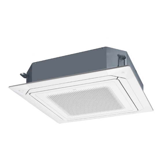
INDOOR UNIT (Cassette Type)
For authorized service personnel only.
INNENGERÄT (Kassettentyp)
Nur für autorisiertes Fachpersonal.
UNITÉ INTÉRIEURE (type cassette)
Pour le personnel agréé uniquement.
UNIDAD INTERIOR (Tipo casete)
UNITÀ INTERNA (tipo a cassetta)
UNIDADE INTERIOR (Tipo Cassete)
Apenas para técnicos autorizados.
MONTAJ KILAVUZU
İÇ ÜNİTE (Kaset Tipi)
Yalnızca yetkili servis personeli için.
PART No. 9371022642-02
MADE IN P.R.C.
[Original instructions]
Advertisement
Table of Contents

Summary of Contents for AirStage AUXM018GLEH
- Page 1 For authorized service personnel only. INSTALLATIONSANLEITUNG INNENGERÄT (Kassettentyp) Nur für autorisiertes Fachpersonal. MANUEL D’INSTALLATION UNITÉ INTÉRIEURE (type cassette) Pour le personnel agréé uniquement. AUXM018GLEH MANUAL DE INSTALACIÓN AUXM024GLEH AUXM030GLEH UNIDAD INTERIOR (Tipo casete) Únicamente para personal de servicio autorizado. AUXK018GLEH...
-
Page 2: Table Of Contents
INSTALLATION MANUAL This mark indicates procedures which, if improperly performed, CAUTION might possibly result in personal harm to the user, or damage PART No. 9371022642-02 to property. VRF system indoor unit (Cassette type) Read carefully all security information before use or install the air conditioner. Do not attempt to install the air conditioner or a part of the air conditioner by yourself. -
Page 3: Accessories
2.3. Accessories Description Model Application Installation in a space of 56 mm or greater Panel spacer UTG-BKXA-W is possible by using panel spacer when the WARNING height behind the ceiling is low. For installation purposes, be sure to use the parts supplied by the manufacturer or other Install the plate at outlet when carrying out prescribed parts. -
Page 4: Installation Dimension
• Refrigerant piping and drain piping positions. (unit: mm) 3.2. Installation dimension Ceiling height is as shown in the figure. 256 mm or more (AUXM018,024,030) 298 mm or more (AUXK018,024,030,034,036,045,054) Gas pipe Drain pipe Liquid pipe Strong and durable ceiling Drain pipe 1,500 mm (Connect the attached... -
Page 5: Pipe Installation
3.3.4. Leveling 4.3.1. Flaring • Using a level, or vinyl hose Use special flare tool exclusive for R410A. filled with water, fine adjust Drain pipe (1) Cut the connection pipe to Check if [L] is so that the body is level. the necessary length with a flared uniformly •... -
Page 6: Installing Heat Insulation
Working procedure 4.4. Installing heat insulation (1) Install the attached drain hose to the drain port of the body. Install the hose band from the top of the hose within the graphic display area. Secure firmly with the hose band. CAUTION (2) Use vinyl adhesive agent to glue the drain piping (PVC pipe VP25) which is prepared After checking for gas leaks (refer to the Installation Manual of the outdoor unit), perform... -
Page 7: Electrical Wiring
A. Current breaker requirements 6. ELECTRICAL WIRING • MCA: Minimum Circuit Ampacity Model • MFA: Maximum Fuse Ampacity AUXM018GLEH 0.24 A WARNING When the power crossover wiring is done, AUXM024GLEH 0.29 A Electrical work must be performed in accordance with this Manual by a person certified make it so that the total of the MCA of the under the national or regional regulations. -
Page 8: Unit Wiring
6.3.2. Transmission and Remote controller cable 6.3. Unit wiring Transmission cable Remote controller cable • Before attaching the cable to terminal block. 30 mm 30 mm 6.3.1. Power supply cable Shield 20 mm cable (no film) 45 mm Earth (Ground) cable •... -
Page 9: Optional Parts Wiring
6.5.2. Power indicator lamp status X1, X2: Transmission cable Power indicator lamp (Green) Status contents Lit when the power is turned on. Fast flashing (every 0.1 sec- There is a fault with the communication board or the ond) main board. The indoor unit is turned off and power is supplied Blinking (repeat 3 seconds ON from the External power supply unit (optional) to the... - Page 10 When connected to Apply voltage terminals of multiple indoor units with a connected unit, [In the case of “Pulse” input] be sure to make a branch outside the indoor unit using a pull box, etc. as shown on below Connector Input signal Command example.
-
Page 11: Field Setting
● When connecting with unit equipped with a power supply • If working in an environ- Table A ment where the wireless Rotary switch Rotary switch P.C.B remote controller can be Address Address setting setting used, the addresses can REF AD SW IU AD SW Connected also be set using the... -
Page 12: Function Setting
Function 7.3. Function setting Function Setting number Default Details number Single Switch the setting method of • FUNCTION SETTING can be performed with the wired or wireless remote controller. setpoint auto auto mode to single or dual (The remote controller is optional equipment) Auto mode mode (cooling/heating). -
Page 13: Error Codes
11. ERROR CODES If you use a wired type remote controller, error codes will appear on the remote controller display. If you use a wireless remote controller, the lamp on the photodetector unit will output error codes by way of blinking patterns. See the lamp blinking patterns and error codes in the table below.


Need help?
Do you have a question about the AUXM018GLEH and is the answer not in the manual?
Questions and answers