Table of Contents
Advertisement
Quick Links
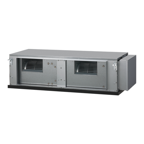
ARXC72GATH
ARXC90GATH
TM
INSTALLATION MANUAL
INSTALLATIONSANLEITUNG
MANUEL D'INSTALLATION
APPAREIL INTÉRIEUR (Type à conduit)
MANUAL DE INSTALACIÓN
Únicamente para personal de servicio autorizado.
MANUALE DI INSTALLAZIONE
A uso esclusivo del personale tecnico autorizzato.
ΕΓΧΕΙΡΙΔΙΟ ΕΓΚΑΤΑΣΤΑΣΗΣ
ΕΣΩΤΕΡΙΚΗ ΜΟΝΑΔΑ (Τύπος αγωγού)
Μόνο για εξουσιοδοτημένο τεχνικό προσωπικό.
MANUAL DE INSTALAÇÃO
РУКОВОДСТВО ПО УСТАНОВКЕ
Только для авторизованного обслуживающего персонала.
INDOOR UNIT (Duct type)
For authorized service personnel only.
INNENGERÄT (Kanaltyp)
Nur für autorisiertes Fachpersonal.
Pour le personnel agréé uniquement.
UNIDAD INTERIOR (Tipo de ducto)
UNITÀ INTERNA (tipo a condotto)
UNIDADE INTERIOR (Tipo de duto)
Apenas para técnicos autorizados.
ВНУТРЕННИЙ МОДУЛЬ (Короб)
MONTAJ KILAVUZU
İÇ ÜNİTE (Kanal tipi)
Yalnızca yetkili servis personeli için.
PART NO. 9365748145
Advertisement
Table of Contents

Related Manuals for AirStage ARXC90GATH


Summary of Contents for AirStage ARXC90GATH
-
Page 1: Installation Manual
Pour le personnel agréé uniquement. MANUAL DE INSTALACIÓN UNIDAD INTERIOR (Tipo de ducto) ARXC72GATH Únicamente para personal de servicio autorizado. ARXC90GATH MANUALE DI INSTALLAZIONE UNITÀ INTERNA (tipo a condotto) A uso esclusivo del personale tecnico autorizzato. ΕΓΧΕΙΡΙΔΙΟ ΕΓΚΑΤΑΣΤΑΣΗΣ ΕΣΩΤΕΡΙΚΗ ΜΟΝΑΔΑ (Τύπος αγωγού) Μόνο... -
Page 2: Table Of Contents
INSTALLATION MANUAL This mark indicates procedures which, if improperly performed, CAUTION might possibly result in personal harm to the user, or damage to PART NO. 9365748145 property. VRF system indoor unit (Duct type) Read carefully all security information before use or install the air conditioner. Do not attempt to install the air conditioner or a part of the air conditioner by yourself. -
Page 3: Accessories
2.3. Accessories 2.4. Optional parts The following options are available. WARNING Description Model No. Application For installation purposes, be sure to use the parts supplied by the manufacturer or External output wire 9379529013 For output port other prescribed parts. The use of non-prescribed parts can cause serious accidents For control input port External input wire D 9368779016... -
Page 4: Installation Dimension
3.3.2. Installing hangers 3.2. Installation dimension Suspend the indoor unit by referring to the following fi gures. Provide a service hole for inspection purposes as shown below. Do not place any wiring or illumination in the service space, as they will impede service. 1,550 mm INSTALLATION DIMENSIONS 1 1,410 mm... -
Page 5: Pipe Installation
3.3.4. Mounting the duct Thicknesses of Annealed Copper Pipes (R410A) Follow the procedure in the following fi gure to install the ducts. Pipe outside diameter [mm (in.)] Thickness [mm] *3 Material 6.35 (1/4) 0.80 1,251 mm 9.52 (3/8) 0.80 COPPER *1 ... -
Page 6: Pipe Connection
Pipe outside diam- Width across fl ats of Flare nut [mm (in.)] Tightening torque [N·m (kgf·cm)] Width across fl ats eter [mm (in.)] Flare nut [mm] 6.35 (1/4) dia. 16 to 18 (160 to 180) 6.35 (1/4) 9.52 (3/8) dia. 32 to 42 (320 to 420) 9.52 (3/8) 12.70 (1/2) dia. -
Page 7: Installing Heat Insulation
Accessories 4.4. Installing heat insulation Drain hose Hose band Drain hose For main drain port (Large) (Large) insulation • Install the coupler heat insulation after completing the refrigerant leak check (for details, Drain hose Hose band Drain hose refer to the Installation Manual for the outdoor unit). For safety drain port (Small) (Small) -
Page 8: Electrical Wiring
ARXC72GATH 5.55 A for the unit. An insuffi cient power supply circuit or improperly performed electrical work ARXC90GATH 6.55 A can cause serious accidents such as electric shock or fi re. Before starting work, check that power is not being supplied to the all units. -
Page 9: Wiring Method
B. For strand wiring 6.2. Wiring method (1) Use ring terminals with insulating sleeves as shown in the fi gure below to connect to the terminal block. EXAMPLE (2) Securely clamp the ring terminals to the cables using an appropriate tool so that the cables do not come loose. -
Page 10: Connection Of Wiring
6.5. Airfl ow changing 6.4. Connection of wiring When apply external static pressure less than 150Pa (ARXC72) or 200Pa (ARXC90) on (1) Remove the control box cover and install each connection cable. the model, please follow the methods below to connect relay wire. (1) Disconnect the PCB wire connector from Fan motor wire connector. -
Page 11: External Input And External Output (Optional Parts)
● Dry contact terminal ([CNA02], [CNA04]) 6.6. External input and external output (Optional When a power supply is unnecessary at the input device you want to connect, use the Dry parts) contact terminal ([CNA02], [CNA04]). P.C.B Controller PCB CNA02 Ch 1 Ch 2 CNA04 Ch 3... - Page 12 ● When function setting is “Forced stop” mode. (3) Connection methods [In the case of “Edge” input] • Wire modifi cation Connector Input signal Command Remove insulation from wire attached to wire kit connector. Remove insulation from fi eld supplied cable. Use crimp type insulated butt connector to OFF →...
-
Page 13: Remote Sensor (Optional Parts)
6.7. Remote sensor (Optional parts) 6.8. IR receiver unit (Optional parts) • For the installation method, please refer to the INSTALLATION MANUAL of remote • For the installation method, please refer to the INSTALLATION MANUAL of IR receiver sensor. unit. Connection methods Connection methods •... -
Page 14: Field Setting
Table A 7. FIELD SETTING Rotary Rotary Address Address There are 3 methods for address setting by FIELD SETTING as follows. Switch Setting Switch Setting Set by either of the methods. Each setting method is described (1) to (3) below. REF AD SW IU AD SW (1) IU AD, REF AD SW settings .... -
Page 15: Custom Code Setting
7.2. Custom code setting 7.4. Function setting Selecting the custom code prevents the indoor unit mix-up. • FUNCTION SETTING can be performed with the wired or wireless remote controller. (Up to 4 codes can be set.) (The remote controller is optional equipment) Perform the setting for both the indoor unit and the remote controller. -
Page 16: Test Run
Error indications 8. TEST RUN Wired Remote Controller Error Error contents OPERATION TIMER lamp FILTER code lamp (green) (orange) lamp (red) 8.1. Test run using Outdoor unit (PCB) Indoor unit power supply • Refer to the Installation Manual for the outdoor unit if the PCB for the outdoor unit is to abnormal be used for the test run.
Need help?
Do you have a question about the ARXC90GATH and is the answer not in the manual?
Questions and answers