Table of Contents
Advertisement
Quick Links
ABYA12GATH/ABHA12GATH
ABYA14GATH/ABHA14GATH
ABYA18GATH/ABHA18GATH
ABYA24GATH/ABHA24GATH
INSTALLATION MANUAL
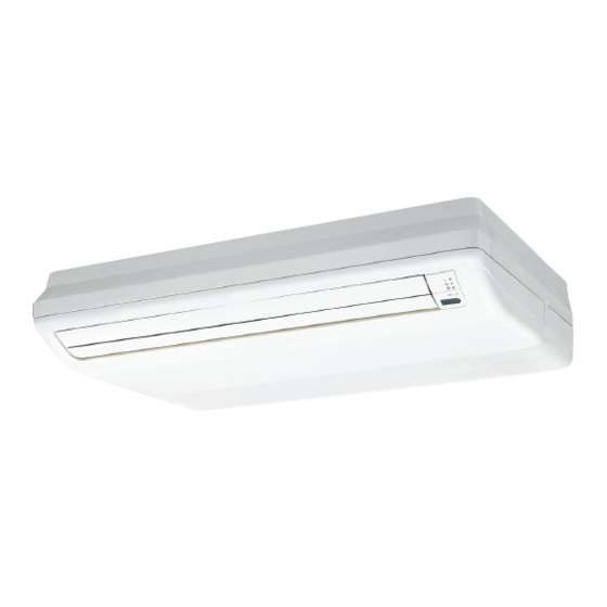
INDOOR UNIT (Floor / Ceiling type)
For authorized service personnel only.
INSTALLATIONSANLEITUNG
INNENGERÄT (Boden / Decken-Typ)
Nur für autorisiertes Fachpersonal.
MANUEL D'INSTALLATION
APPAREIL INTÉRIEUR (type sol / plafonnier)
Pour le personnel agréé uniquement.
MANUAL DE INSTALACIÓN
UNIDAD INTERIOR (tipo suelo / techo)
Únicamente para personal de servicio autorizado.
MANUALE DI INSTALLAZIONE
UNITÀ INTERNA (tipo a pavimento / soffi tto)
A uso esclusivo del personale tecnico autorizzato.
ΕΓΧΕΙΡΙΔΙΟ ΕΓΚΑΤΑΣΤΑΣΗΣ
ΕΣΩΤΕΡΙΚΗ ΜΟΝΑΔΑ (Τύπου Δαπέδου / Οροφής)
Μόνο για εξουσιοδοτημένο τεχνικό προσωπικό.
MANUAL DE INSTALAÇÃO
UNIDADE INTERIOR (Modelo de chão / tecto)
Apenas para técnicos autorizados.
РУКОВОДСТВО ПО УСТАНОВКЕ
ВНУТРЕННИЙ МОДУЛЬ (Напольного / Потолочного типа)
Только для авторизованного обслуживающего персонала.
MONTAJ KILAVUZU
Yalnızca yetkili servis personeli için.
PART NO. 9367701100-02
İÇ ÜNİTE (Tavan / Yer tipi)
Advertisement
Table of Contents

Subscribe to Our Youtube Channel
Related Manuals for AirStage ABYA12GATH


Summary of Contents for AirStage ABYA12GATH
-
Page 1: Installation Manual
Pour le personnel agréé uniquement. MANUAL DE INSTALACIÓN UNIDAD INTERIOR (tipo suelo / techo) Únicamente para personal de servicio autorizado. MANUALE DI INSTALLAZIONE ABYA12GATH/ABHA12GATH UNITÀ INTERNA (tipo a pavimento / soffi tto) ABYA14GATH/ABHA14GATH A uso esclusivo del personale tecnico autorizzato. ABYA18GATH/ABHA18GATH ΕΓΧΕΙΡΙΔΙΟ... -
Page 2: Table Of Contents
INSTALLATION MANUAL This mark indicates procedures which, if improperly performed, CAUTION might possibly result in personal harm to the user, or damage to PART NO. 9367701100-02 property. VRF system indoor unit (Floor / Ceiling type) Read carefully all security information before use or install the air conditioner. Contents Do not attempt to install the air conditioner or a part of the air conditioner by yourself. -
Page 3: Accessories
Name and Shape Q’ty Application 2.3. Accessories Drain hose For installing drain pipe VP25 (O.D.32, I.D.25) WARNING For installation purposes, be sure to use the parts supplied by the manufacturer or other prescribed parts. The use of non-prescribed parts can cause serious accidents Hose Band For installing drain hose such as the unit falling, water leakage, electric shock, or fi... -
Page 4: Installation Dimension
CAUTION 3.3. Installation the unit Install the indoor unit, power supply cable, transmission cable, and remote controller cable at least 1 m away from a television or radio receivers. The purpose of this is to WARNING prevent TV reception interference or radio noise. (Even if they are installed more than 1 m apart, you could still receive noise under some signal conditions.) Install the air conditioner in a location which can withstand a load of at least 5 times the weight of the main unit and which will not amplify sound or vibration. -
Page 5: Pipe Installation
B. Under ceiling type B-4. Installing indoor unit Using the installation template, drill holes for piping and suspension bolts (for holes). Reset the hex bolts as shown in the fi gure Hex bolt Drilling position 8 to 13 Indoor unit for suspension Installation bolt... -
Page 6: Pipe Requirement
4.3.3. Pipe connection 4.2. Pipe requirement Connect the silencer pipe to the small (liquid) pipe. Centering the pipe against port on the indoor unit, turn the fl are nut with your hand. CAUTION Be sure that the small pipe is completely installed before connecting the large pipe. Refer to the Installation Manual of the outdoor unit for description of the length of connecting pipe or for difference of its elevation. -
Page 7: Installing Heat Insulation
INSTALL THE DRAIN HOSE 4.4. Installing heat insulation Working procedure 1) Install the attached drain hose to the drain port of the body. Install the hose band from CAUTION the top of the hose within the graphic display area. Secure fi rmly with the hose band. 2) Use vinyl adhesive agent to glue the drain piping (PVC pipe VP25) which is prepared After checking for gas leaks (refer to the Installation Manual of the outdoor unit), on site or piping socket. -
Page 8: Electrical Wiring
B. Under ceiling type CAUTION Be sure to arrange the drain hose so that it is leveled lower than the drain hose connect- Earth (Ground) the unit. ing port of the indoor unit. Do not connect the earth (ground) cable to a gas pipe, water pipe, lightning rod, or a GOOD PROHIBITED telephone earth (ground) cable. -
Page 9: Wiring Method
6.2. Wiring method WARNING When using solid core cables, do not use the ring terminal. If you use the solid core EXAMPLE cables with the ring terminal, the ring terminal’s pressure bonding may malfunction and cause the cables to abnormally heat up. Outdoor unit or RB unit *1 B. -
Page 10: Connection Of Wiring
(4) Wiring CAUTION * When there is 1 transmission cable or remote controller cable, fasten it the same way as shown in the fi gure with a cable tie (medium). To peel the fi lm from the lead cable, use a dedicated tool that will not damage the conductor cable. - Page 11 ● Apply voltage terminal ([CNA01], [CNA03]) P.C.B When a power supply must be provided at the input device you want to connect, use the Apply voltage terminal ([CNA01], [CNA03]). CNA02 DC power supply P.C.B 12 to 24V Load resistance CNA01 P.C.B CNA02 Load...
-
Page 12: Field Setting
Cable tie (Field supply) * When the forced stop is triggered, indoor unit stops and Operation/Stop operation by a Clamp (Clamp with other cables) remote controller is restricted. * When forced stop function is used with forming a remote controller group, connect the same equipment to each indoor unit within the group. -
Page 13: Custom Code Setting
(1) Indoor unit address Custom code setting for indoor unit Rotary switch (IU AD × 1) ......Factory setting “0” Set the DIP switch SET 3 SW1, SW2, referring to the Table B. Rotary switch (IU AD × 10) ....Factory setting “0” When connecting multiple indoor units to 1 refrigerant system, set the address at IU AD SW as shown in the Table A. - Page 14 Function details 7.4.1. Button name and function Function Function Setting number Default Details number Default ○ Adjust the fi lter cleaning interval Filter indicator notifi cation. If the notifi cation is too early, Longer interval change to setting 01. If the notifi cation is too late, change to setting 02.
-
Page 15: Mount The Cover Plate And The Intake Grille
(2) Others 8.2. Mount the cover plate (Right) Indication pattern (1) Cut a pipe exit hole in the right plate. This is only when the pipe exits from the right Indicator Name Indication pattern side. (This operation is not required when the protrusion is on the top or rear.) OPERATION indicator lamp (Green) Function number;... -
Page 16: Test Run
9. TEST RUN 11. ERROR CODES If you use a wired type remote controller, error codes will appear on the remote controller display. If you use a wireless remote controller, the lamp on the photodetector unit will 9.1. Test run using Outdoor unit (PCB) output error codes by way of blinking patterns.
Need help?
Do you have a question about the ABYA12GATH and is the answer not in the manual?
Questions and answers