
Subscribe to Our Youtube Channel
Related Manuals for PPI Zenex Pro


Summary of Contents for PPI Zenex Pro
- Page 1 Zenex Pro Zenex Pro User Manual Advanced Universal Self-Tune PID Temperature Controller with Programmable Timer User Manual...
- Page 2 Zenex Pro User Manual CONTENTS 1. FRONT PANEL LAYOUT 2. BASIC OPERATION 3. SET UP MODE : ACCESS & OPERATION PAGE-10 : I / O CONFIGURATION PARAMETERS PAGE-12 : OP2 FUNCTION PARAMETERS PAGE-13: OP3 FUNCTION PARAMETERS 7. PAGE-14 : PID CONTROL PARAMETERS 8.
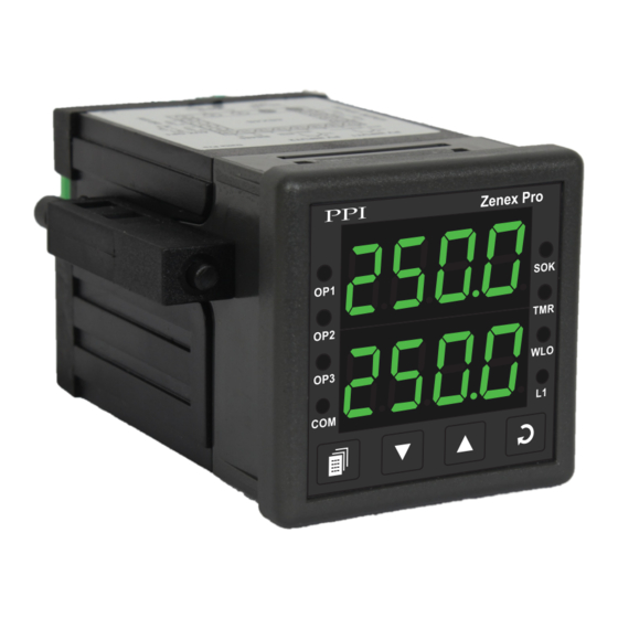
- Page 3 Zenex Pro User Manual Section 1 FRONT PANEL LAYOUT The controller front panel comprises of digital readouts, LED indicators and tactile keys as shown in Figure 1.1 below. Figure 1.1 Zenex Pro Upper Readout Output-1 Status Indicator Soak Timer Status Indicator...
- Page 4 Zenex Pro User Manual Indicator Status Flashes while the Soak Timer is counting down. Glows steadily while the Soak Timer is outside the Timer Start Band or Hold Band. Glows while the Lower Readout shows the Balance Soak Time. Water Level Status. Flashes if water level is LOW.
- Page 5 Zenex Pro User Manual Section 2 BASIC OPERATIONS POWER-UP Upon power-up the controller executes the following sequence of operations. Checks for Sensor Fault. If the connected sensor type is RTD Pt100 and the selected sensor type is any of thermocouples or ·...
- Page 6 Zenex Pro User Manual PV Error Indications The process value is said to be in error if it exceeds the minimum / maximum range specified for the selected Input sensor type or if the sensor is disconnected (Open or Broken).
- Page 7 Zenex Pro User Manual The Operator Parameters are described in Table 2.2. Note that the parameters presented on operator page depend upon the functions selected / enabled. The operator parameter list mainly includes : Soak Start / Abort Command, if Soak Time feature is enabled.
- Page 8 Zenex Pro User Manual OP2 Function : Auxiliary Control Settings Parameter Description AUXILIARY CONTROL SETPOINT (Min. Range - SP) Positive (+) or Negative (-) offset to Control Setpoint (SP) for (Max. Range - SP) defining Auxiliary Setpoint. for selected Input...
- Page 9 Zenex Pro User Manual Control Setpoint (SP) Locking Settings Parameter Description SETPOINT LOCKING Set to Yes to lock the SP editing on the Lower Readout.
- Page 10 Zenex Pro User Manual Section 3 SET-UP MODE : ACCESS AND OPERATION The various parameters are arranged in different groups, called PAGES, depending upon the functions they represent. Each group is assigned a unique numeric value, called PAGE NUMBER, for its access.
- Page 11 Zenex Pro User Manual MASTER LOCKING The controller facilitates locking all the PAGES (except Operator PAGE) by applying Master Lock Code. Under Locking, the parameters are available for view only and cannot be adjusted. The Master Lock, however does not lock the operator parameters.
- Page 12 Zenex Pro User Manual Section 4 PAGE 10 : I / O CONFIGURATION PARAMETERS Table 4.1 Settings Parameter Description Default Value INPUT TYPE Refer Table 4.2 Refer Table 4.2 for various available ‘Input Types’ along with their (Default : Type K) respective Ranges and Resolutions.
- Page 13 Zenex Pro User Manual Settings Parameter Description Default Value Min. Range to SETPOINT LOW LIMIT Setpoint High for the This parameter sets the minimum limit on the Control Setpoint selected Input Type value. (Default : -200) Setpoint Low to SETPOINT HIGH LIMIT Max.
- Page 14 Zenex Pro User Manual Section 5 PAGE 12 : OP2 FUNCTION PARAMETERS Table 5.1 Settings Parameter Description Default Value OUTPUT-2 FUNCTION SELECTION None None OP2 module not installed or function not used. Alarm Alarm OP2 relay activates as Alarm status.
- Page 15 Zenex Pro User Manual Settings Parameter Description Default Value LOGIC Normal Normal The Alarm output (Relay/SSR) remains ON under alarm condition; OFF otherwise. Useful for Audio / Visual Alarm. Reverse Reverse The Alarm output (Relay / SSR) remains OFF under alarm...
- Page 16 Zenex Pro User Manual OP2 Function : Blower / Compressor Control Settings Parameter Description Default Value OFFSET VALUE 0 to 250 or Sets a positive (+) offset to the SP to define the ‘Blower / 0.0 to 25.0 Compressor Setpoint’.
- Page 17 Zenex Pro User Manual Section 6 PAGE 13 : OP3 FUNCTION PARAMETERS Table 6.1 Settings Parameter Description Default Value None OUTPUT-3 FUNCTION SELECTION Alarm None OP2 module not installed or function not used. Control Alarm OP2 relay activates as Alarm status.
- Page 18 Zenex Pro User Manual Settings Parameter Description Default Value LOGIC Normal Normal The Alarm output (Relay/SSR) remains ON under alarm condition; OFF otherwise. Useful for Audio / Visual Alarm. Reverse Reverse (Default : Normal) The Alarm output (Relay / SSR) remains OFF under alarm condition;...
- Page 19 Zenex Pro User Manual Section 7 PAGE 14 : PID CONTROL PARAMETERS Table 7.1 Settings Parameter Description Default Value % OUTPUT POWER Not Applicable This is a view only parameter that facilitates the indication of ‘% Output Power’ computed by the controller PID algorithm. The...
- Page 20 Zenex Pro User Manual Settings Parameter Description Default Value DERIVATIVE TIME (For ‘PID’ Control) It is desired that the controller should respond to any dynamic changes in the process conditions (like variations in load, power supply fluctuations, etc.) fast enough so as retain the process 0 to 250 Seconds value near the setpoint.
- Page 21 Zenex Pro User Manual Section 8 PAGE 15 : SOAK TIMER PARAMETERS (Refer end of this section for detailed Soak Timer Operation) Table 8.1 Settings Parameter Description Default Value TIMER ENABLE Soak Timer function and Start / Abort commands are enabled.
- Page 22 Zenex Pro User Manual Settings Parameter Description Default Value POWER-FAIL RECOVERY METHOD Abort Abort The timer operation is suspended until a new start command is (Re)Start issued. Start Continue The timer re-runs the complete soak time. (Default : Continue) Continue The Soak Timer resumes operation for the balance time.
- Page 23 Zenex Pro User Manual Power-fail Recovery Modes The timer facilitates 3 different power-fail recovery modes, viz., Continue, Re-start and Abort. In Continue mode, the timer resumes to execute the balance soak time once the PV is detected within Hold Band. In Re-start mode, the timer executes the complete set time all over again.
- Page 24 Zenex Pro User Manual Section 9 PAGE 11 : SUPERVISORY PARAMETERS Table 9.1 Settings Parameter Description Default Value TUNE / OPTIMIZE COMMAND (For PID Control Mode only) Set to ‘Yes’ for initiating Tune / Optimize operation. (Default : TUNE / OPTIMIZE ABORT COMMAND (For PID Control Mode only) Set to ‘Yes’...
- Page 25 Zenex Pro User Manual Settings Parameter Description Default Value PERMISSION FOR OP2/OP3 SETPOINT EDITING Disable ON OPERATOR PAGE Enable This parameter allows the user to enable (permit) or disable (restrict) the adjustment of the Setpoint for OP2 / OP3 functions.
- Page 26 Zenex Pro User Manual Settings Parameter Description Default Value None PARITY Parity setting for serial communication protocol Even (Default : Even) COMMUNICATION WRITE ENABLE The Read/Write parameters can be accessed for both reading and writing. (Default : Yes) The Read/Write parameters can only be accessed for reading.
- Page 27 Zenex Pro User Manual Section 10 MECHANICAL INSTALLATION OUTER DIMENSIONS AND PANEL CUTOUT The Figure 10.1 shows the controller outer dimensions. Figure 10.1 48mm 94mm (1.89in) (3.70in) Zenex Pro 7mm (0.276in) Front View Side View PANEL CUTOUT The Figure 10.2 shows the panel cutout requirements for a single controller.
- Page 28 Zenex Pro User Manual PANEL MOUNTING Follow the steps below for mounting the controller on panel: 1. Prepare a square cutout to the size shown in Figure 10.2. 2. Remove the Panel Mounting Clamp from the controller Enclosure and insert the rear of the controller housing through the panel cutout from the front of the mounting panel.
- Page 29 Zenex Pro User Manual Section 11 ELECTRICAL CONNECTIONS WARNING MISHANDLING / NEGLIGENCE CAN RESULT IN PERSONAL DEATH OR SERIOUS INJURY. 1. The user must rigidly observe the Local Electrical Regulations. 2. Do not make any connections to the unused terminals for making a tie-point for other wires (or for any other reasons) as they may have some internal connections.
- Page 30 Zenex Pro User Manual DESCRIPTIONS The back panel connections are described as under: PV INPUT : RTD Pt100, 3-wire / Thermocouple (Terminals : 17, 16, 15) Connect 3-wire RTD Pt100 sensor or Thermocouple as shown below. Figure 11.2 (a) Figure 11.2 (b)
- Page 31 Zenex Pro User Manual mA / V Output The Positive (+) of mA / V is available at Terminal 14 & the Negative (-) at Terminal 13. Relay Output Potential-free Relay changeover contacts NO (Normally Open) and C (Common) rated 10A/240 VAC (resistive load).
- Page 32 Zenex Pro User Manual 85~264 VAC : Power Supply (Terminals 1, 2) The controller is supplied with power connections suited for 85 to 264 VAC line supply. Use well-insulated copper conductor wire of the size not smaller than 0.5mm for power supply connections. Connect Line (Phase) supply line to terminal 1 and the Neutral (Return) supply line to terminal 2 as shown in Figure 11.6 below.
- Page 33 Zenex Pro User Manual Process Precision Instruments 101, Diamond Industrial Estate, Navghar, Vasai Road (E), Dist. Palghar - 401 210.Maharashtra, India Sales : 8208199048 / 8208141446 Support : 07498799226 / 08767395333 sales@ppiindia.net, support@ppiindia.net w w w . p p i i n d i a . n e t...
Need help?
Do you have a question about the Zenex Pro and is the answer not in the manual?
Questions and answers