
Related Manuals for PPI HumiTherm Ultra


Summary of Contents for PPI HumiTherm Ultra
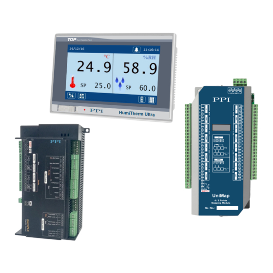
- Page 1 HumiTherm Ultra HumiTherm Ultra User Manual Temperature + Humidity (%RH) Control & Recording System with 8 / 16 Mapping Inputs Touch Operation Panel P P I User Manual...
-
Page 2: Table Of Contents
HumiTherm Ultra User Manual CONTENTS 1. MOUNTING & ELECTRICAL CONNECTIONS : HMI (TOUCH PANEL) 2. MOUNTING & ELECTRICAL CONNECTIONS : microPLC 3. MOUNTING, ELECTRICAL CONNECTIONS & JUMPER SETTINGS : MAPPING 4. BASIC OPERATION & PARAMETERS ORGANIZATION 5. OPERATOR LEVEL PARAMETERS 6. -
Page 3: Mounting & Electrical Connections : Hmi (Touch Panel)
HumiTherm Ultra User Manual Section 1 MOUNTING & ELECTRICAL CONNECTIONS : HMI (TOUCH PANEL) 4.3” Mounting Table 1.1 Dimensions 128(W) X 102(H) X 55(D), mm Overall 121(W) X 95(H), mm Panel Cutout Figure 1.1 5 mm 128 mm 55 mm 4.3”... - Page 4 HumiTherm Ultra User Manual 7” Mounting Table 1.2 Dimensions 206(W) X 136(H) X 44(D), mm Overall 199(W) X 129(H), mm Panel Cutout Figure 1.3 6.5 mm 44 mm 206 mm 199 mm (Panel Cut)
- Page 5 HumiTherm Ultra User Manual 7” Electrical Connections Battery Cover Figure 1.4 PULL COM2 ETHERNET RESET 24VDC Table 1.3 3-Pin Male / Female Connector (5.08 mm pitch) Supply Voltage : 20 to 28 VDC (24 V Nominal) 9 (4.3” HMI) / 15 (7” HMI) Pin D Type Connector RS485 Serial Communication with microPLC &...
-
Page 6: Mounting & Electrical Connections : Microplc
HumiTherm Ultra User Manual Section 2 MOUNTING & ELECTRICAL CONNECTIONS : microPLC Mounting (Base / Wall Mounting) Figure 2.1 179mm 77mm ø5mm Mounting Hole ø5mm Mounting Hole microPLC Electrical Connections Figure 2.2 Standby Main Stby Main Digital Outputs Digital Inputs... - Page 7 HumiTherm Ultra User Manual DESCRIPTIONS The connections are described as under: Figure 2.3 (a) Main Humidity (%RH) Transmitter Input (Terminals : 7,8, 9) 0/1~5V, 0~10V The Controller accepts DC Current (mA) / DC Voltage (V) as Humidity input. The connections are described below.
- Page 8 HumiTherm Ultra User Manual [Optional] Standby Humidity (%RH) Transmitter Input (Terminals : 14, 15, 16, 17) [Optional] Standby Temperature (°C) Sensor / Transmitter Input (Terminals : 18, 19, 20, 21) The Control Unit optionally supports Inputs for Standby (redundant) Humidity & Temperature sensor / transmitter. The Connection detail are the same as for main sensor / transmitter described above.
-
Page 9: Mounting, Electrical Connections & Jumper Settings : Mapping
HumiTherm Ultra User Manual Section 3 MOUNTING, ELECTRICAL CONNECTIONS & JUMPER SETTINGS : MAPPING Mounting (Base / Wall Mounting) Figure 3.1 210mm 205mm ø5mm Mounting Hole ø5mm Mounting Hole Mapping Electrical Connections Figure 3.2 MAP 1 MAP 2 MAP 3... - Page 10 HumiTherm Ultra User Manual Map Inputs Each of the °C and %RH inputs are identical from wiring connection viewpoint. The descriptions below apply to all the inputs with no deviations. Make sure that proper jumper settings are made for each input for the selected input type as described later in this ection.
- Page 11 HumiTherm Ultra User Manual SERIAL COMMUNICATION PORT Figure 3.5 Mapping RS485 Port The wiring connections for interfacing the HMI with mapping unit is shown in the figure 3.5. INPUT TYPE : JUMPER SETTINGS The Mapping Unit (UniMap) is supplied with 8 (...
- Page 12 HumiTherm Ultra User Manual The jumper setting arrangement comprises of Pins & Shorting-Link as shown in the figure below. The figure also depicts how to mount the Shorting-Link for a particular jumper setting. Figure 3.7 Pins Shorting Shorting Link Shorting Link...
-
Page 13: Basic Operation & Parameters Organization
HumiTherm Ultra User Manual Section 4 BASIC OPERATION & PARAMETER ORGANIZATION Upon Power up to the HMI, after a few initialization screens, the Main (Home) screen is displayed. This is the screen that shall be used most often and is described below in details. - Page 14 HumiTherm Ultra User Manual Process Status Screen This screen shows various rocess Alarm status and the information regarding working / fa ure of various Main and Standby Sensors (Temperature & %RH) & Control Gadgets (Air Heater, Boiler Heater & Compressor). The contents on this screen are dependent on whether Standby Sensors and / or Standby Control Gadgets are installed or not.
- Page 15 HumiTherm Ultra User Manual Output Status This screen shows : Heating & Humidification % output power On-Off Status for Main & Standby (if installed) Air Heater, Boiler Heater (Humidifier) & Compressor Alarm Relay Status Record Status is screen shows the total record sto rage capacity, numbers of current stored records and available free space.
- Page 16 HumiTherm Ultra User Manual MAP VIEW BUTTON This is a touch button that opens up screen(s) to view process values for mapping input s. The installed mapping input s could be 8 (4 Map Points : 4T + 4RH) or 16 (8...
- Page 17 HumiTherm Ultra User Manual Upon touching one of the levels, a keyboard for password entry pops-up as shown below. The user must touch the text screen to make it editable. Upon touch the text screen shows a blue band as shown below.
- Page 18 HumiTherm Ultra User Manual Each access level may have sub levels for convenient parameter grouping. The Table . lists various parameters with levels and sub levels. Table 4.1 Level Sub-Level Parameters Temperature Set Value Low Deviation Alarm High Deviation Alarm...
- Page 19 HumiTherm Ultra User Manual Level Sub-Level Parameters Mode (ON, OFF, PV Based, SP Based), Boundary SP or Compressor SP, Time Delay, Hysteresis Compressor Zone Select (Single, Dual) Float Detection Enable (Yes / No), Low Level Logic (Open / Close) Thermostat...
- Page 20 HumiTherm Ultra User Manual PARAMETER SETTINGS There are 3 types of parameters; Numeric, String Option and Commands. The setting methods for different types are described below. Numeric Parameters This type of parameter has 2 fields; Name Field Value Field &...
- Page 21 HumiTherm Ultra User Manual Command Parameters This type of parameter is used to perform specific actions like Start / Abort tuning, Delete Records, etc. A touch Push Button image is provided for issuance of command as shown in the figure. Usually an acknowledgment window with OK button pops up to indicate the action performed.
-
Page 22: Operator Level Parameters
HumiTherm Ultra User Manual Section 5 OPERATOR LEVEL PARAMETERS Operator 25.0 60.0 Temperature Set Value Range : Temperature Setpoint ow imit to Temperature Setpoint High Limit Default : 25.0 °C This is the Setpoint Value for temperature control loop. This value can also be set on home screen if enabled through the parameter SP Edit on Home Screen. - Page 23 HumiTherm Ultra User Manual %RH High Deviation Alarm Range : 0.2 to 99.9 % Default : 2.0 % This Parameter sets a Positive Deviation (offset) limit with respect to the ‘ %RH Set Value ’. The Alarm is activated if the measured %RH value exceeds this limit.
-
Page 24: Supervisory Level Parameters
HumiTherm Ultra User Manual Section 6 SUPERVISORY LEVEL PARAMETERS Supervisory Recording Recording Interval Range : 1 to 250 Minutes Default : 5 Minutes The Controller generates and stores periodic records at the interval set by this parameter. ‘Delete Record’ Command This command is issued using the touch push button. - Page 25 HumiTherm Ultra User Manual (Available only if the controller is supplied with GSM Module Version) Supervisory SMS Alert GSM Machine ID Range : 1 to 128 Default : 1 This parameter can be used to assigned a unique ID to the machine (chamber) to identify the source of SMS alert.
- Page 26 HumiTherm Ultra User Manual Lock Position Options : Solenoid O , Solenoid O Default : Solenoid OFF Set this parameter to ‘Solenoid ON’, if the chamber door is locked when the solenoid is turned ON (energized). Set this parameter to ‘Solenoid OFF’, if the chamber door is locked when the solenoid is turned OFF (de-energized).
- Page 27 HumiTherm Ultra User Manual Supervisory Maintenance Repair Acknowledge In case the control system is installed with standby set of sensors and / or control gadgets, the controller automatically switches to the Standby set should any of the sensors / control gadgets of the Main set fail. After fixing the fault / failure, the user must acknowledge the same to the controller for resuming the operation with the main set.
-
Page 28: Factory Level Parameters
HumiTherm Ultra User Manual Section 7 FACTORY LEVEL PARAMETERS Factory Temperature Input Settings Input Type Options RTD Pt100, 0 to 20 mA, 4 to 20 mA, 0 to 5 V, 0 to 10 V, 1 to 5 V Default : RTD Pt100 Select Input type in accordance with the type of Temperature sensor / transmitter connected for measurement. - Page 29 HumiTherm Ultra User Manual Display Range Low (Available for DC Linear Volts & mA Inputs only) Range : -199.9 to Range High Default : 0.0 This parameter is the rocess alue that correspond to the Signal Low value from the transmitter. Refer Appendix-A : DC Linear Signal Interface for details.
- Page 30 HumiTherm Ultra User Manual Low Alarm Deviation Range : 0.2 to 99.9 °C Default : 2.0 °C This parameter sets the maximum permissible process value deviation below the temperature setpoint. If the temperature exceeds this deviation, the alarm is activated.
- Page 31 HumiTherm Ultra User Manual Dual Zone PID Constants are described below. Heat Zone Proportional Band Range : 0.1 to 999.9 °C Default : 50.0 °C Sets proportional gain for Heat Pre-dominant zone. Heat Zone Integral Time Range : 0 to 3600 Sec.
- Page 32 HumiTherm Ultra User Manual Derivative Time Range : 0 to 600 Sec. Default : 16 Sec. Sets derivative time constant in Seconds. Setting the value to 0, cuts-off derivative action. The parameters below are applicable to both Single Zone Dual Zone &...
- Page 33 HumiTherm Ultra User Manual Factory Input Settings Input Type Options 0 to 20 mA, 4 to 20 mA, 0 to 5 V, 0 to 10 V, 1 to 5 V Default : 0 to 5 V Select Input type in accordance with the type of sensor / transmitter connected for measurement.
- Page 34 HumiTherm Ultra User Manual Display Range Low Range : -199.9 to Range High Default : 0.0 This parameter is the rocess alue that correspond to the Signal Low value from the transmitter. Refer Appendix-A : DC Linear Signal Interface for details.
- Page 35 HumiTherm Ultra User Manual High Alarm Deviation Range : 0.2 to 99.9 % Default : 2.0 % This parameter sets the maximum permissible process value deviation above setpoint. If the exceeds this deviation, the alarm is activated. Hysteresis Range : 0.1 to 99.9 Default : 0.2...
- Page 36 HumiTherm Ultra User Manual Dual Zone PID Constants are described below. Heat Zone Proportional Band Range : 0.1 to 999.9 %RH Default : 50.0 %RH Sets proportional gain for Heat Pre-dominant zone. Heat Zone Integral Time Range : 0 to 3600 Sec.
- Page 37 HumiTherm Ultra User Manual Derivative Time Range : 0 to 600 Sec. Default : 16 Sec. Sets derivative time constant in Seconds. Setting the value to 0, cuts-off derivative action. The parameters below are applicable to both Single Zone Dual Zone &...
- Page 38 HumiTherm Ultra User Manual Factory Compressor For detailed description and functioning of the parameters related to compressor operation, refer Appendix-B : Compressor Switching Strategies. Mode Options : Continuous O , Continuous O , SP Based ON-OFF, PV Based ON-OFF Default : Continuous OFF Compressor SP Range : 0.0 to 100.0...
- Page 39 HumiTherm Ultra User Manual Factory Water Level Float Detection Enable Options No, Yes Default : No Set to ‘Yes’ if Float Switch is mounted for detecting Low water level. Float Low Level Logic Options : Switch Open, Switch Close Default : Switch Close If set to ‘Switch Close’, the water level is considered Low if the switch is CLOSE.
- Page 40 HumiTherm Ultra User Manual Factory Door Open Detection Enable Options No, Yes Default : No Set to ‘Yes’ if Door Open detection switch is mounted. Door Open Logic Options : Switch Open, Switch Close Default : Switch Close If this parameter is set to ‘Switch Close’, the door is detected as Open if the switch is CLOSE.
- Page 41 HumiTherm Ultra User Manual Detection Enable Options No, Yes Default : No Set to ‘Yes’ if provision is made for running the controller on an auxiliary power sources like battery or inverter and a Switch is mounted for detecting main power source failure.
- Page 42 HumiTherm Ultra User Manual Factory Standby Control Gadgets Fail Detect Time (Min) Range : 0 to 250 Min. Default : 10 Min This parameter sets a timer. If either temperature or %RH process value exceeds “High Alarm Deviation” limit, the timer starts counting down.
- Page 43 HumiTherm Ultra User Manual Factory Mapping Configuration Select Mapping Inputs Options : 4T + 4RH, 8T + 8RH Default : 4T + 4RH Select this parameter depending upon whether 8 input (4 Temperature + 4 %RH) or 16 input (8 Temperature + 8 %RH) unit is installed for mapping.
- Page 44 HumiTherm Ultra User Manual If this parameter is set to ‘Disable’, the Alarm is not suppressed during the start-up Alarm conditions. High Alarm Set Value Range : -199.9 to 600.0 °C Default : 0 °C This parameter sets a common...
- Page 45 HumiTherm Ultra User Manual Input Type Settings Default 0.00 to Signal High 0 to 20 mA 0.00 4.00 to Signal High 4 to 20 mA 4.00 0.00 to Signal High 0 to 50 mV 0.00 0.0 to Signal High 0 to 200 mV 0 to 1.25 V...
- Page 46 HumiTherm Ultra User Manual Factory Mapping Alarm Settings Low Alarm Set Value Range : 0 to 100.0 %RH Default : 0 %RH This parameter sets a common %RH value limit below which an alarm is generated. Low Alarm Hysteresis Range : 0.1 to 50.0 %RH Default : 2.0 %RH...
- Page 47 HumiTherm Ultra User Manual Factory Mapping Input Settings 100.0 All the arameter settings, except Zero Offset, on this screen are Common for all %RH Inputs. Input Type Options : 0 to 20 mA, 4 to 20 mA, 0 to 50 mV, 0 to 200 mV, 0 to 1.25 V, 0 to 5 V, 1 to 5 V, 0 to 10 V Default : 0 to 5 V Select Input type in accordance with the type of sensors / transmitters connected for measurement on all %RH Inputs.
- Page 48 HumiTherm Ultra User Manual Input Type Settings Default Signal Low to 20.00 0 to 20 mA 20.00 Signal Low to 20.00 4 to 20 mA 20.00 Signal Low to 50.00 0 to 50 mV 50.00 Signal Low to 200.0 0 to 200 mV 200.0...
-
Page 49: Appendix-A : Dc Linear Signal Interface
. Most PPI instruments, thus, provide programmable Signal Type and Range to facilitate interface with a variety of transmitters. A few industry standard signal types and ranges offered by the PPI instruments are: 0-50mV, 0- 200mV, 0-5 V, 1-5 V, 0-10V, 0-20 mA, 4-20 mA, etc. - Page 50 HumiTherm Ultra User Manual The following examples illustrate appropriate parameter value selections. Example 1: Pressure Transmitter producing 4 to 20 mA 0 to 5 psi Y (psi) Presume the pressure is to be measured Range High 5.00 with 0.01 Resolution, that is 0.00 to 5.00 psi.
- Page 51 HumiTherm Ultra User Manual The following table list various parameters related to DC linear signal input interface & their respective locations. Navigation Parameter Name (Where to Locate) Main & Standby Temperature Control Sensors Temperature Input Type Temperature Signal Low Factory...
-
Page 52: Appendix-B : Compressor Setting Parameters
COMPRESSOR SETTING PARAMETERS Compressor Switching Strategies The PPI “Temperature + Humidity” composite controllers offer different programmable strategies for compressor switching to meet different design approaches by the manufacturers of Humidity Chambers. The various strategies and the implementations are described here. - Page 53 HumiTherm Ultra User Manual 4. PV Based Strategy In this strategy, the compressor is switched to cool down the chamber air temperature. The controller switches the compressor ON or OFF based on the comparison between the chamber temperature value and the Temperature Refer Figure below.
- Page 54 HumiTherm Ultra User Manual °C PV (Temperature) 21.0 Compressor Switch-ON Level Compressor Switch-OFF Level 20.0 19.8 Temperature SP = 20.0°C Compressor Set-point = 1.0°C Compressor Hysteresis = 1.2°C Compressor Switch-ON Level = 20.0 + 1.0 = 21.0°C Compressor Switch-OFF Level = 21.0 - 1.2 = 19.8°C...
-
Page 55: Appendix-C : Standby Sensors
HumiTherm Ultra User Manual APPENDIX - C STANDBY SENSORS If the Controller is supplied with Standby Sensors option, two additional analog inputs are provided for interfacing an additional set of temperature & %RH sensors as standby. That is, there are two sets of Sensors; Main & Standby. - Page 56 HumiTherm Ultra User Manual The following table list various parameters related to Standby Sensors & their respective locations. Navigation Parameter Name (Where to Locate) Sensor Fail Detection Limit Temperature Low Factory Standby Sensor Inputs %RH Low Switch to Standby Sensor...
-
Page 57: Appendix-D : Standby Control Gadget
HumiTherm Ultra User Manual APPENDIX - D STANDBY CONTROL GADGETS If the Controller is supplied with Standby Control Gadgets option, 5 additional digital outputs are provided for interfacing an additional set of Control Gadgets as standby. That is, there are two sets of Control Gadgets; Main & Standby. - Page 58 HumiTherm Ultra User Manual The controller uses Measured Temperature & Low Water Level detection for detecting the control gadget failure. Temperature Based Detection For temperature based detection, the controller uses High Deviation Alarm & a Programmable Fail Detect Time (Minutes). If the measured temperature value crosses the High Deviation Limit &...
- Page 59 HumiTherm Ultra User Manual Main & Standby Sets Failure As long as this condition prevails, the controller behaves like an indicator by keeping all its outputs off. Replace / repair the faulty control gadget(s) and then use Repair Acknowledge button to bring controller to its normal operation mode.
-
Page 60: Appendix-E : Door Lock
HumiTherm Ultra User Manual APPENDIX - E DOOR LOCK If the Controller is supplied with Door Lock option, an additional digital output is provided for operating an electro-mechanical (Solenoid driven) locking system through an external relay / contactor. For automatic operation of the lock by the controller, the cabinet door must also be installed with Door Open detect switch that should be connected to the controller digital input labeled 'Door Open'. -
Page 61: Appendix-F : Digital Input & Output
HumiTherm Ultra User Manual APPENDIX - F DIGITAL INPUTS & OUTPUTS DIGITAL INPUTS The microPLC Control Unit incorporates interfaces for potential-free digital inputs for various functions described below. Power Fail This Digital Input is used if provision is made for running the controller on an auxiliary power sources like battery or inverter and a Switch is mounted for detecting main power source failure. - Page 62 HumiTherm Ultra User Manual Main Set Select Standby Set Select These Digital Output are fitted and functional only if controller is supplied with Standby Output feature. The digital outputs control external electrical switches (like contactors) that, in turn, control the power to the relay / SSR sets that drive control gadgets (Heater, Humidifier &...
- Page 63 HumiTherm Ultra User Manual Process Precision Instruments 101, Diamond Industrial Estate, Navghar, Vasai Road (E), Dist. Palghar - 401 210.Maharashtra, India 0250 - 2391722/33/37/42 07498799226, 09321985369 sales@ppiindia.net, support@ppiindia.net w w w . p p i i n d i a . n e t...
Need help?
Do you have a question about the HumiTherm Ultra and is the answer not in the manual?
Questions and answers