
Related Manuals for PPI Zenex


Summary of Contents for PPI Zenex
- Page 1 Universal Self-Tune PID Temperature Controller with Programmable Timer User Manual...
-
Page 2: Table Of Contents
User Manual CONTENTS For Size 48X48 1. FRONT PANEL LAYOUT 2. BASIC OPERATION 3. SET UP MODE : ACCESS & OPERATION I / O CONFIGURATION PARAMETERS OP2 FUNCTION PARAMETERS OP3 FUNCTION PARAMETERS 7. PID CONTROL PARAMETERS 8. SOAK TIMER PARAMETERS 9. -
Page 3: Front Panel Layout
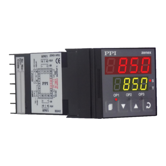
User Manual Section 1 FRONT PANEL LAYOUT Figure 1.1 Upper Readout zenex Soak Status Indicator Lower Readout Balance Soak Time Indicator Output-2 Indicator Output-1 Indicator Output-3 Indicator PAGE Key ENTER Key DOWN Key UP Key The front panel contains digital readouts, LED indicators and keys. - Page 4 User Manual KEYS The Table 1.2 lists the four front panel keys and the associated function. Table 1.2 Symbol Function PAGE Press to enter or exit set-up mode. Press to decrease the parameter value. Pressing once decreases the value by one count; keeping DOWN pressed speeds up the change.
-
Page 5: Basic Operation
User Manual Section 2 BASIC OPERATIONS POWER-UP Upon power-up all displays and indicators are lit on for approximately 3 seconds. This is followed by the indication of the controller model name on the Upper Readout and the firmware version on the Lower Readout, for approximately 1 second. - Page 6 User Manual Table 2.1 Message PV Error Type Over-range PV above Max. Range Under-range PV below Min. Range Open Sensor / RTD broken CONTROL/ALARM STATUS UNDER PV ERROR CONDITIONS a) The tuning, if in progress, is aborted. b) The Soak Timer, if in progress, enters in Pause (halt) state.
- Page 7 User Manual Table 2.2 Settings Parameter Description TIMER START COMMAND Set to Yes to start Soak Timer. Not available if timer already running. TIMER ABORT COMMAND Set to Yes to abort a running timer. 00.05 to 60.00 M:S TIME DURATION 00.05 to 99.55 H:M...
- Page 8 User Manual OP2 Function : Blower / Compressor Control Settings Parameter Description BLOWER / COMPRESSOR SETPOINT 0 to 250 or Positive (+) offset to Control Setpoint (SP) for defining Blower / 0.0 to 25.0 Compressor Setpoint. OP3 Function : Alarm-2...
-
Page 9: Set Up Mode : Access & Operation
User Manual Section 3 SET-UP MODE : ACCESS AND OPERATION The various parameters are arranged in different groups, called PAGES, depending upon the functions they represent. Each group is assigned a unique numeric value, called PAGE NUMBER, for its access. - Page 10 User Manual MASTER LOCKING The controller facilitates locking all the PAGES (except Operator PAGE) by applying Master Lock Code. Under Locking, the parameters are available for view only and cannot be adjusted. The Master Lock, however does not lock the operator parameters.
-
Page 11: I / O Configuration Parameters
User Manual Section 4 I / O CONFIGURATION PARAMETERS Table 4.1 Settings Parameter Description Default Value INPUT TYPE Refer Table 4.2 Refer Table 4.2 for various available ‘Input Types’ along with their (Default : Type K) respective Ranges and Resolutions. - Page 12 User Manual Settings Parameter Description Default Value Min. Range to SETPOINT LOW LIMIT Setpoint High for the This parameter sets the minimum limit on the Control Setpoint selected Input Type value. (Default : -200) Setpoint Low to SETPOINT HIGH LIMIT Max.
-
Page 13: Op2 Function Parameters
User Manual Section 5 OP2 FUNCTION PARAMETERS Table 5.1 Settings Parameter Description Default Value OUTPUT-2 FUNCTION SELECTION None None OP2 module not installed or function not used. Alarm Alarm OP2 relay activates as Alarm status. Control Auxiliary Control Blower OP2 relay activates as Auxiliary control status. - Page 14 User Manual Settings Parameter Description Default Value LOGIC Normal Normal The Alarm output (Relay/SSR) remains ON under alarm condition; OFF otherwise. Useful for Audio / Visual Alarm. Reverse Reverse The Alarm output (Relay / SSR) remains OFF under alarm...
- Page 15 User Manual OP2 Function : Blower / Compressor Control Settings Parameter Description Default Value OFFSET VALUE 0 to 250 or Sets a positive (+) offset to the SP to define the ‘Blower / 0.0 to 25.0 Compressor Setpoint’. (Default : 0)
-
Page 16: Op3 Function Parameters
User Manual Section 6 OP3 FUNCTION PARAMETERS Table 6.1 Settings Parameter Description Default Value OUTPUT-3 FUNCTION SELECTION None None OP2 module not installed or function not used. Alarm Alarm Control OP2 relay activates as Alarm status. Auxiliary Control (Default : None) OP2 relay activates as Auxiliary control status. - Page 17 User Manual Settings Parameter Description Default Value LOGIC Normal Normal The Alarm output (Relay/SSR) remains ON under alarm condition; OFF otherwise. Useful for Audio / Visual Alarm. Reverse Reverse (Default : Normal) The Alarm output (Relay / SSR) remains OFF under alarm condition;...
-
Page 18: Pid Control Parameters
User Manual Section 7 PID CONTROL PARAMETERS Table 7.1 Settings Parameter Description Default Value % OUTPUT POWER Not Applicable This is a view only parameter that facilitates the indication of ‘% Output Power’ computed by the controller PID algorithm. The... - Page 19 User Manual Settings Parameter Description Default Value DERIVATIVE TIME (For ‘PID’ Control) It is desired that the controller should respond to any dynamic changes in the process conditions (like variations in load, power supply fluctuations, etc.) fast enough so as retain the process 0 to 250 Seconds value near the setpoint.
-
Page 20: Soak Timer Parameters
User Manual Section 8 SOAK TIMER PARAMETERS (Refer end of this section for detailed Soak Timer Operation) Table 8.1 Settings Parameter Description Default Value TIMER ENABLE Soak Timer function and Start / Abort commands are enabled. (Default : Soak Timer function and Start / Abort commands are disabled. - Page 21 User Manual Settings Parameter Description Default Value POWER-FAIL RECOVERY METHOD Continue Continue The Soak Timer resumes operation for the balance time. (Re)Start Start The timer re-runs the complete soak time. Abort Abort (Default : Continue) The timer operation is suspended until a new start command is issued.
- Page 22 User Manual Power-fail Recovery Modes The timer facilitates 3 different power-fail recovery modes, viz., Continue, Re-start and Abort. In Continue mode, the timer resumes to execute the balance soak time once the PV is detected within Hold Band. In Re-start mode, the timer executes the complete set time all over again.
-
Page 23: Supervisory Parameters
User Manual Section 9 SUPERVISORY PARAMETERS Table 9.1 Settings Parameter Description Default Value TUNE / OPTIMIZE COMMAND (For PID Control Mode only) Set to ‘Yes’ for initiating Tune / Optimize operation. (Default : TUNE / OPTIMIZE ABORT COMMAND (For PID Control Mode only) Set to ‘Yes’... - Page 24 User Manual Settings Parameter Description Default Value PERMISSION FOR OP2/OP3 SETPOINT EDITING Enable ON OPERATOR PAGE Disable This parameter allows the user to enable (permit) or disable (restrict) the adjustment of the Setpoint for OP2 / OP3 functions. (Default :...
- Page 25 User Manual Settings Parameter Description Default Value COMMUNICATION WRITE ENABLE The Read/Write parameters can be accessed for both reading and writing. (Default : Yes) The Read/Write parameters can only be accessed for reading. That is, the parameter values cannot be altered through serial...
-
Page 26: Hardware Assembly And Configurations
User Manual Section 10 HARDWARE ASSEMBLY AND CONFIGURATIONS The Figure 10.1 below shows the controller outer-case viewed with front label upright. ELECTRONIC ASSEMBLY The basic electronics assembly (without any plug-in modules), comprises of 3 Printed Circuit Boards (PCB). When viewed from the front;... - Page 27 User Manual Figure 10.2 ‘UP’ inscribed on topside CPU PCB N / C N / O N / O L A Y L i n e a r Display N / O N / C L i n P l a...
- Page 28 User Manual MOUNTING PLUG-IN MODULES The controller supports up to 3 plug-in modules, viz. Output-2 Module (Relay / SSR or DC Linear), Output-3 Module (Relay / SSR or DC Linear) and Option Module (RS485 Serial Port or Digital Input for Auxiliary Setpoint selection). These modules are either pre-fitted while the controller is shipped from the factory or can be fitted by the user later.
- Page 29 User Manual Table 10.1 Output Type Jumper Setting - A Jumper Setting - B Relay DC Linear Voltage / Current Module The DC Linear Module is factory configured for either Current or Voltage output. The current output can be configured for 0-20 mA or 4-20 mA and similarly the voltage output can be configured for 0-5 V or 0-10 V through parameter settings.
- Page 30 User Manual Figure 10.5 Mounting Output-2 Module Plug & Socket Connector Output Module Projected Parts Slots Power Supply Board z e n Front Label Upright Figure 10.6 Mounting Output-3 Module Plug & Socket Connector Output Module Projections CPU Board...
- Page 31 User Manual The plug for the Serial Communication or Auxiliary SP Selection module is located on the Power-supply PCB. The Figure 10.7 below illustrates how to plug-in the Serial Communication/Auxiliary SP module. To plug (or unplug) the module simply insert (or remove) the socket into (or from) the plug.
-
Page 32: Mechanical Installation
User Manual Section 11 MECHANICAL INSTALLATION The following precautions should be strictly observed while installing the controller: 1. The place of installation should be free of corrosive/combustible gases and electrically conductive pollution. 2. Ensure that the place of installation is not subject to rapid ambient changes that can cause condensation. Also the Ambient Temperature and Relative Humidity surrounding the controller should not exceed the maximum specified for the proper operation of the controller. - Page 33 User Manual PANEL MOUNTING Follow the steps below for mounting the controller on panel: 1. Prepare a square cutout to the size shown in Figure 11.2. 2. Remove the Panel Mounting Clamp from the controller Enclosure. 3. Insert the rear of the controller housing through the panel cutout from the front of the mounting panel.
-
Page 34: Electrical Connections
User Manual Section 12 ELECTRICAL CONNECTIONS Refer connection diagram shown on the left side of the enclosure. The diagram shows the terminals viewed from the REAR SIDE with the controller label upright. Figure 12.1 2 Output Version zenex 48X48... - Page 35 User Manual TEMPERATURE SENSOR INPUT Connect Thermocouple or 3-wire RTD Pt100 sensor as shown below. Figure 12.2 (a) Figure 12.2 (b) Thermocouple Thermocouple Connect Thermocouple Positive (+) to terminal 1 and Negative (-) to terminal 2 as shown in Figure 12.2 (a). Use correct type of extension lead wires or compensating cable.
- Page 36 User Manual Figure 12.4 (a) Figure 12.4 (b) Relay Output SSR Output Relay Output SSR Output Refer Figure 12.4(a) for Output-2 & Figure 12.4(b) for Output-3 connections. Figure 12.5 POWER SUPPLY The controller accepts single phase, 50/60 Hz Line Voltage ranging from 85 VAC to 264 VAC. Use well-insulated copper conductor wire of the size not smaller than 0.5mm for power supply...
- Page 37 User Manual zenex96 zenex 96X96...
-
Page 38: Front Panel Layout
zenex96 User Manual Section 1 FRONT PANEL LAYOUT Figure 1.1 zenex96 Upper Readout Lower Readout Balance Soak Soak Status Time Indicator Indicator Output-2 Indicator Output-1 Indicator Output-3 Indicator PAGE Key ENTER Key DOWN Key UP Key The front panel contains digital readouts, LED indicators and keys. READOUTS The Upper Readout is a 4 digit, 7-segment bright red LED display and usually displays the PV (Process Value). - Page 39 zenex96 User Manual KEYS The Table 1.2 lists the four front panel keys and the associated function. Table 1.2 Symbol Function Press to enter or exit set-up mode. PAGE Press to decrease the parameter value. Pressing once decreases the value by one count; keeping DOWN pressed speeds up the change.
-
Page 40: Hardware Assembly And Configurations
zenex96 User Manual Section 2 HARDWARE ASSEMBLY AND CONFIGURATIONS The Figure 2.1 below shows the controller outer-case viewed with front label upright. ELECTRONIC ASSEMBLY The basic electronics assembly (without any plug-in modules), comprises of 3 Printed Circuit Boards (PCB). The CPU PCB, Power-supply PCB and the Display PCB is behind the bezel. - Page 41 zenex96 User Manual OUTPUT-2 & 3 : Jumper Settings Besides the parameter settings, the Output-2 & 3 configuration requires jumper settings selections as shown in the Table 2.2 below. Figure 2.2 illustrates mounting of Output Modules. Table 2.2 Output-2 & 3 Jumper Settings Output Type Jumper Setting - A Jumper Setting - B...
- Page 42 zenex96 User Manual The plug for the Serial Communication or Auxiliary SP Selection module is located on the Power-supply PCB. The Figure 2.3 below illustrates how to plug-in the Serial Communication/Auxiliary SP module. To plug (or unplug) the module simply insert (or remove) the socket into (or from) the plug.
-
Page 43: Electrical Connections
Refer connection diagram shown on the left side of the enclosure. The diagram shows the terminals viewed from the REAR SIDE with the controller label upright. Figure 3.1 2 Output Version 3 Output Version zenex 96 X 96 96X96 DC Linear Version zenex... - Page 44 zenex96 User Manual TEMPERATURE SENSOR INPUT Connect Thermocouple or 3-wire RTD Pt100 sensor as shown below. Figure 3.2 (a) Figure 3.2 (b) Thermocouple Thermocouple Connect Thermocouple Positive (+) to terminal 1 and Negative (-) to terminal 2 as shown in Figure 3.2 (a). Use correct type of extension lead wires or compensating cable.
- Page 45 zenex96 User Manual Figure 3.4 (a) Figure 3.4 (b) Relay Output SSR Output Relay Output SSR Output Refer Figure 3.4(a) for Output-2 & Figure 3.4(b) for Output-3 connections. Figure 3.5 POWER SUPPLY The controller accepts single phase, 50/60 Hz Line Voltage ranging from 85 VAC to 264 VAC. Use well-insulated copper conductor wire of the size not smaller than 0.5mm for power supply connections.
- Page 46 Process Precision Instruments 101, Diamond Industrial Estate, Navghar, Vasai Road (E), Dist. Palghar - 401 210.Maharashtra, India 0250 - 2391722/33/37/42 07498799226, 09321985369 sales@ppiindia.net, support@ppiindia.net w w w . p p i i n d i a . n e t...
Need help?
Do you have a question about the Zenex and is the answer not in the manual?
Questions and answers
Need dealer list
The dealer list for PPI Zenex includes:
1. Vision Industrial Product
Contact Person: Mr. Dharmesh Bhatt
Address: 32, Gopal Charan Industrial Globe Road No-05, GIDC, Kathwada, Industrial Estate, Ahmedabad - 382430, Gujarat, India.
This answer is automatically generated