Table of Contents
Advertisement
Quick Links
LabCon
LabCon Map + Printer
User Manual
Multi-Purpose Temperature Controller
Recording + 4 Channel Mapping + Printer Interface
User Manual
Advertisement
Table of Contents

Related Manuals for PPI LabCon


Summary of Contents for PPI LabCon
- Page 1 LabCon LabCon Map + Printer User Manual Multi-Purpose Temperature Controller Recording + 4 Channel Mapping + Printer Interface User Manual...
-
Page 2: Table Of Contents
LabCon Map + Printer User Manual CONTENTS 1. FRONT PANEL LAYOUT 2. BASIC OPERATION 3. OPERATOR PARAMETERS 4. SUPERVISORY PARAMETERS 5. FACTORY PARAMETER 6. PANEL MOUNTING AND ELECTRICAL CONNECTIONS APPENDIX-A : DC LINEAR SIGNAL INTERFACE... -
Page 3: Front Panel Layout
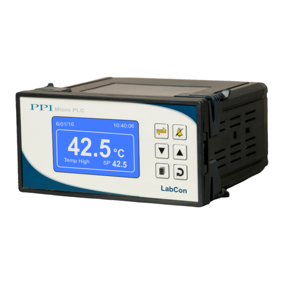
LabCon Map + Printer User Manual Section 1 FRONT PANEL LAYOUT The Controller front panel comprises of Graphic Readout and Membrane Keys as shown in Figure 1.1 below. Figure 1.1 Micro PLC Graphic 6/01/16 10:40:06 Readout 25.0 °C Keys 25.0... -
Page 4: Basic Operation
LabCon Map + Printer User Manual Section 2 BASIC OPERATIONS POWER-UP DISPLAY Figure 2.1 (a) Figure 2.1 (b) Self Checking... LabCon REAL TIME CLOCK H/W Version 02.02 SD MEMORY CARD COMM. LINK F/W Version 01.01 EEPROM Upon power-up the controller display shows screen depicted in Figure 2.1(a) for 2 Seconds. The controller runs through a self- test sequence for checking its Real Time Clock, SD Memory Card, internal Communication Link and Parameter Storage Memory (EEPROM). - Page 5 LabCon Map + Printer User Manual This is the default Run Mode screen that shows easured Temperature Value, et Temperature Value, Calendar Date, Clock Time and Alarm / Process Status as illustrated in Figure 2.2 (a) above. If Soak Timer function is enabled, the un ode screen also shows the elapsed time as illustrated in Figure 2.2 (b) above.
- Page 6 LabCon Map + Printer User Manual Process Status Screen The Process Status Screen is shown upon pressing (Scroll) key from Main Screen or upon acknowledging a new Alarm by pressing (Acknowledge) key. As depicted in Figure 2.5; the screen shows Temperature Alarm Status, Door Open / Close Status, the Heater Output (Heating) in % &...
-
Page 7: Operator Parameters
LabCon Map + Printer User Manual Section 3 OPERATOR PARAMETERS The Operator Parameters are accessible under PASSWORD 0. The list includes parameters for adjusting Control Setpoint, Alarm Setpoints & Zero-offset for Control & Mapping Channels. If Soak Timer is enabled then Time Interval value & Timer Start / Abort commands are also available. - Page 8 LabCon Map + Printer User Manual Settings Parameter Description (Default Value) TIME START COMMAND >> TIME ABORT COMMAND >> (Available only if Soak Timer is Enabled) These two commands are mutually exclusive. (Default : No) Set to Yes to start Soak Timer, if not already started.
-
Page 9: Supervisory Parameters
LabCon Map + Printer User Manual Section 4 SUPERVISORY PARAMETERS The various parameters have been assembled in different groups under the default factory password 123. Refer Table 4.1 below for a quick summary of parameters under different groups. Each parameter has been described in subsequent sections. - Page 10 LabCon Map + Printer User Manual SETPOINT HI LIMIT >> SETPOINT HI LIMIT >> HEAT CTRL ACTION >> 600.0 100.0 Next Parameter Desired Parameter Desired Parameter Value Press UP/DOWN Press UP/DOWN Press ENTER Key Keys to Select Keys to adjust...
- Page 11 LabCon Map + Printer User Manual SUPERVISORY RECORDING Settings Parameter Description (Default Value) REC. INTERVAL (MIN) >> The Controller generates and stores periodic records at the 0 to 250 Min interval set by this parameter. The time units are in Minutes.
- Page 12 LabCon Map + Printer User Manual SUPERVISORY CONTROL Settings Parameter Description (Default Value) TUNE >> (Available for Heat Only / Heat+Cool Control Strategy) (Default : Set ‘Yes’ to activate and ‘No’ to abort the Tuning operation. Min Range for the Selected SETPOINT LO LIMIT >>...
- Page 13 LabCon Map + Printer User Manual Heat + Cool Heat + Cool Heat Only Control Control Zone : Single Control Zone : Dual CZ PROP BAND >> PROPORTIONAL BAND >> PROPORTIONAL BAND >> Proportional Band for Cool Pre-dominant zone 0.1 to 999.9 0.1 to 999.9...
- Page 14 LabCon Map + Printer User Manual PROPORTIONAL BAND Sets proportional gain (% power per unit error). Defined in same units and resolution as that for PV. INTEGRAL TIME Sets integral time constant in Seconds. Setting the value to 0, cuts-off the integral action.
- Page 15 LabCon Map + Printer User Manual SUPERVISORY PRINT EVENT The controller generates instantaneous records of several Events such as Alarm Toggle, Power-up, Door Open, etc. These records are in addition to the records generated at regular user set time interval. The printouts of event generated records are marked with specific abbreviations for differentiation.
-
Page 16: Factory Parameter
LabCon Map + Printer User Manual Section 5 FACTORY PARAMETERS The various parameters have been assembled in various group under the default factory password 321. Refer Table 5.1 below for a quick summary of parameters under different groups. Each parameter has been described in subsequent sections. - Page 17 LabCon Map + Printer User Manual Notes 1. The Last Parameter in the selected Group rolls back to the ‘SELECT GROUP’ screen again to avoid re-entering the password in case multiple parameters need to be set under different Group. 2. Select group ‘EXIT’ & set parameter ‘EXIT SET-UP MODE’ to ‘YES’ for returning to Main Display Mode. Alternately use Set-up Key for instant revert to Main Display Mode.
- Page 18 LabCon Map + Printer User Manual FACTORY MAPPING PARAMETERS Settings Parameter Description (Default Value) MAPPING POINTS >> The Controller supports up to 3 or 4 sensor inputs (depending on 0 to 4 version supplied) for Mapping. This parameter allows the user to (Default : ) select the desired numbers for Mapping.
- Page 19 LabCon Map + Printer User Manual Table 5.2 Range (Min. to Max.) What it means Resolution Type J Thermocouple 0 to +960°C Type K Thermocouple -200 to +1376°C Type T Thermocouple -200 to +385°C Fixed Type R Thermocouple 0 to +1770°C 1°C...
- Page 20 HEAT COOL SELECT The PPI “Multi-Purpuse Temperature Controller” provides control outputs for driving, both, heating & cooling sources. The user can enable any one or both outputs depending upon the test equipment type and application. If both outputs are enabled (by setting the parameter ‘Control Strategy’...
- Page 21 LabCon Map + Printer User Manual 4. PV Based Strategy In this strategy, the compressor is switched to cool down the air temperature. The controller switches the compressor ON or OFF based on the comparison between the Measured & Set Temperature values. Refer Figure 5.3 below.
- Page 22 LabCon Map + Printer User Manual Figure 5.4 °C PV (Temperature) 21.0 20.0 19.8 Compressor Switch-ON Level Compressor Switch-OFF Level Temperature SP = 20.0°C Compressor Set-point = 1.0°C Compressor Status Compressor Hysteresis = 1.2°C Compressor Switch-ON Level = 20.0 + 1.0 = 21.0°C Compressor Switch-OFF Level = 21.0 - 1.2 = 19.8°C...
- Page 23 LabCon Map + Printer User Manual Settings Parameter Description (Default Value) Control Strategy : Cool Only TIME DELAY (SEC) >> 0 to 1000 Sec (Default : Sec) Control Strategy : Heat + Cool COMPRESSOR STRATEGY >> CONT. OFF CONT. ON...
- Page 24 LabCon Map + Printer User Manual FACTORY SOAK TIMER PARAMETERS Settings Parameter Description (Default Value) HOLDBACK STRATEGY >> None PV based timer pause is not required. None Timer is paused if PV is outside holdband above SP. Down Both Down (Default : None) Timer is paused if PV is outside holdband below SP.
- Page 25 LabCon Map + Printer User Manual FACTORY DOOR OPEN Settings Parameter Description (Default Value) ENABLE >> Set to ‘Yes’ if Switch is mounted for detecting door Open / Close position. (Default : SWITCH LOGIC >> Close : Door Open CLOSE : DOOR OPEN The Door position is considered Open if the switch is CLOSE.
- Page 26 LabCon Map + Printer User Manual FACTORY PASSWORD Settings Parameter Description (Default Value) CHANGE PASSWORD >> The Controller is shipped from the factory with a default password (321) for accessing the parameters reserved for the equipment manufacturer. However, if required the password can be changed 2000 to 2999 by setting the new value for this parameter.
-
Page 27: Panel Mounting And Electrical Connections
LabCon Map + Printer User Manual Section 6 PANEL MOUNTING AND ELECTRICAL CONNECTIONS WARNING MISHANDLING / NEGLIGENCE CAN RESULT IN PERSONAL DEATH OR SERIOUS INJURY. PANEL CUTOUT Figure 6.1 Panel Cutout 78 X 154 mm -0, +0.5 mm PANEL MOUNTING Follow the steps below for mounting the instrument on panel : 1. - Page 28 LabCon Map + Printer User Manual Figure 6.2 SOAK START MAP-4 MAP-3 MAP-2 MAP-1 CTRL BATTERY DOOR Sensor Inputs CH - X COMMON RS485 Control Outputs Supply COMM 18~32VDC 22 23 24 25 26 27 28 29 30 31 32 33...
- Page 29 LabCon Map + Printer User Manual Figure 6.4 (b) 0/1~5V, 0~10V Temperature Transmitter with DC Voltage (V) Output T1 T2 T3 T4 The Figures 6.4(b) depicts wiring connections for voltage output transmitter. An external Excitation Voltage source should be used for powering the transmitter.
- Page 30 LabCon Map + Printer User Manual The controller Communication Port is RS485 and requires a similar port at the host (master) end. If, however, the host port is different (say, RS232), use appropriate protocol converter (say, RS485-RS232) for interface. For reliable noise free communication, use a pair of twisted wires inside screened cable as shown in Figure 6.5. The wire should have less than 100 ohms / km nominal DC resistance (Typically 24 AWG or thicker).
- Page 31 (mV/V/mA) and Range. Most PPI instruments, thus, provide programmable Signal Type and Range to facilitate interface with a variety of transmitters. A few industry standard signal types and ranges offered by the PPI instruments are: 0-50mV, 0- 200mV, 0-5 V, 1-5 V, 0-10V, 0-20 mA, 4-20 mA, etc.
- Page 32 LabCon Map + Printer User Manual The following examples illustrate appropriate parameter value selections. Example 1: Pressure Transmitter producing 4 to 20 mA 0 to 5 psi Y (psi) Presume the pressure is to be measured Range High 5.00 with 0.01 Resolution, that is 0.00 to 5.00 psi.
- Page 33 LabCon Map + Printer User Manual Process Precision Instruments 101, Diamond Industrial Estate, Navghar, Vasai Road (E), Dist. Palghar - 401 210.Maharashtra, India 0250 - 2391722/33/37/42 07498799226, 09321985369 sales@ppiindia.net, support@ppiindia.net w w w . p p i i n d i a . n e t...
Need help?
Do you have a question about the LabCon and is the answer not in the manual?
Questions and answers