Advertisement
Table of Contents
- 1 Table of Contents
- 2 Front Panel Layout
- 3 Basic Operation
- 4 Pages & Parameters
- 5 Installation Parameters
- 6 Configuration Parameters
- 7 Supervisory Parameters
- 8 Function Parameters
- 9 Function Parameters
- 10 Pid Control Parameters
- 11 Hardware Assembly and Configuration
- 12 Mechanical Installation
- 13 Electrical Connections
- Download this manual
Advertisement
Table of Contents

Related Manuals for PPI Zenex-ultra


Summary of Contents for PPI Zenex-ultra
- Page 1 Zenex-ultra Ultra Precision (0.01 °C) Self-Tune PID Temperature Controller with Programmable Timer User Manual...
-
Page 2: Table Of Contents
Zenex-ultra User Manual CONTENTS FRONT PANEL LAYOUT BASIC OPERATION PAGES & PARAMETERS INSTALLATION PARAMETERS CONFIGURATION PARAMETERS SUPERVISORY PARAMETERS OP-2 FUNCTION PARAMETERS OP-3 FUNCTION PARAMETERS PID CONTROL PARAMETERS 10. HARDWARE ASSEMBLY AND CONFIGURATION 11. MECHANICAL INSTALLATION 12. ELECTRICAL CONNECTIONS... -
Page 3: Front Panel Layout
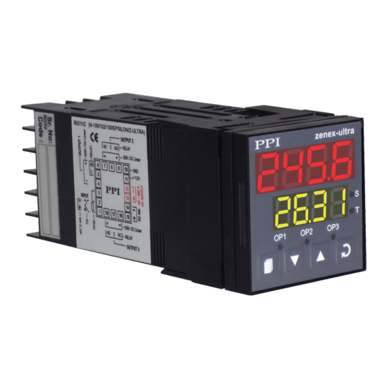
Zenex-ultra User Manual Section 1 FRONT PANEL LAYOUT The controller front panel comprises of digital readouts, LED indicators and membrane keys as shown in Figure 1.1 below. Figure 1.1 zenex-ultra Upper Readout Soak Status Indicator Lower Readout Balance Soak Time Indicator... -
Page 4: Basic Operation
Zenex-ultra User Manual Section 2 BASIC OPERATIONS MAIN DISPLAY MODE After the power-up display sequence, the upper readout starts showing the measured PV (Process Value) and the lower readout displays the SP (Setpoint) in 0.01°C Resolution. This is called the MAIN display mode and this is the one that shall be used most often. The MAIN display mode is depicted in Figure 2.1. -
Page 5: Pages & Parameters
Zenex-ultra User Manual Section 3 PAGES & PARAMETERS ORGANIZATION The controller requires various user settings that determine how the controller will function or operate. These settings are called parameters. The various parameters have been grouped as shown in Table 3.1. Each group is assigned a unique PAGE NUMBER for its access and the parameters within each group are presented depending on the function(s) selected. - Page 6 Zenex-ultra User Manual (examples; Control Mode, Alarm Logic, etc.) have a series of options. If adjusting a numeric value; depressing the UP/DOWN key once, increases/decreases the parameters value by one digit. For parameters having a series of options, depressing the UP/DOWN key once takes you to the next/previous option. In each case, keeping the UP/DOWN key pressed speeds up the rate.
-
Page 7: Installation Parameters
Solid State Relay (SSR) Note: In the zenex-ultra, the Temperature Range is restricted to -19.99 to +102.9°C. This Temperature Range is fixed and not available as settable parameter. The 0.01°C Resolution is available upto 99.99°C. After this, the resolution automatically changes to 0.1°C. -
Page 8: Configuration Parameters
Zenex-ultra User Manual Section 5 CONFIGURATION PARAMETERS The Configuration parameters are contained in PAGE-11 and are factory set to the appropriate default values. However, for specific installations the user may need to alter the values. Altering the configuration parameter values affect either the measured PV and/or the control algorithm implemented by the controller. -
Page 9: Supervisory Parameters
Zenex-ultra User Manual Section 6 SUPERVISORY PARAMETERS The Supervisory parameters are available in PAGE-12 and provides communication parameters to the user and also can be used to exercise control over operator level or to use the controller's in-built ability to improve upon the control performance under conditions that are beyond the self-detection capabilities of the controller. -
Page 10: Function Parameters
Zenex-ultra User Manual Section 7 OP-2 FUNCTION PARAMETERS The Output-2 Function Parameters are available in PAGE-13. The parameters are specified in Table 7.1 below. Table 7.1 Settings Parameter Description (Default Value) ALARM TYPE Process Low Process High Select the Alarm-1 activation type. Selecting ‘None’ will disable the alarm and suppress all the related parameters for Alarm-1. - Page 11 Zenex-ultra User Manual BLOWER FUNCTION AND PARAMETERS The blower on-off operation is depicted in Figure 7.3 below. Figure 7.3 Blower Setpoint Hysteresis Band Blower ON The Blower Setpoint is set as a positive offset to the process setpoint SP. The Blower is switched ON if the PV equals or exceeds the setpoint.
-
Page 12: Function Parameters
Zenex-ultra User Manual Section 8 OP-3 FUNCTION PARAMETERS The Output-3 Function Parameters are available in PAGE-14. The parameters are specified in Table 8.1 below. Table 8 Settings Parameter Description (Default Value) OUTPUT-3 FUNCTION None (Applicable for OP3 hardware module, if fitted) -
Page 13: Pid Control Parameters
Zenex-ultra User Manual Section 9 PID CONTROL PARAMETERS As described in Section 5: Configuration Parameters, the control mode can be set as ON-OFF or PID. If set as PID, the controller allows adjustment of various control related parameters that are grouped in PAGE-15. Note that these parameters are not presented to the user if the set control mode is ON-OFF. - Page 14 Zenex-ultra User Manual Settings Parameter Description (Default Value) DERIVATIVE TIME This parameter value, expressed in seconds, defines how strong the control output level will change in response to the rate of 0 to 250 Seconds change of measured PV. This, in effect, produces larger...
-
Page 15: Hardware Assembly And Configuration
Zenex-ultra User Manual Section 10 HARDWARE ASSEMBLY AND CONFIGURATIONS Figure 10.1 Ventilations Rear Terminals Panel Mounting Clamp Panel Sealing Gasket N / C N / O N / O Bezel L A Y u l t L i n e a r... - Page 16 Zenex-ultra User Manual Figure 10.2 ‘UP’ inscribed on topside CPU PCB N / C N / O N / O L A Y L i n e a r Display N / O N / C L i n u l t...
- Page 17 Zenex-ultra User Manual Figure 10.3 CPU PCB Pins Shorting Link INPUT : Jumper Settings The Input type is user configurable and thus requires, besides parameter selections, proper jumper-settings prior to electrical connections. The jumper settings are provided in the form of Pins & Shorting-Link arrangements on the CPU PCB towards the rear end as shown in Figure 10.3.
- Page 18 Zenex-ultra User Manual Figure 10.4 Relay/SSR Module Table 10.1 Output Type Jumper Setting - A Jumper Setting - B Relay MOUNTING / UN-MOUNTING OF MODULES The Figures 10.5 & 10.6 illustrates how to mount the plug-in Output-2 & Output-3 module, respectively. Notice the orientation of the indicator and a few identifying components shown in figures to help locate the plugs for the modules.
- Page 19 Zenex-ultra User Manual Figure 10.5 Mounting Output-2 Module Plug & Socket Connector Output Module Projected Parts Slots Power Supply Board z e n e x - u l t r a Front Label Upright Figure 10.6 Mounting Output-3 Module Plug & Socket...
- Page 20 Zenex-ultra User Manual The plug for the Serial Communication or Remote Alarm Acknowledgment module is located on the Power-supply PCB. The Figure 10.7 below illustrates how to plug-in the Serial Communication/Remote Alarm Acknowledgment module. To plug (or unplug) the module simply insert (or remove) the socket into (or from) the plug.
-
Page 21: Mechanical Installation
Zenex-ultra User Manual Section 11 MECHANICAL INSTALLATION The following precautions should be strictly observed while installing the indicator: 1. The place of installation should be free of corrosive/combustible gases and electrically conductive pollution. 2. Ensure that the place of installation is not subject to rapid ambient changes that can cause condensation. Also the Ambient Temperature and Relative Humidity surrounding the indicator should not exceed the maximum specified for the proper operation of the Indicator. - Page 22 Zenex-ultra User Manual PANEL MOUNTING Follow the steps below for mounting the Indicator on panel: 1. Prepare a square cutout to the size shown in Figure 11.2. 2. Remove the Panel Mounting Clamp from the Indicator Enclosure. 3. Insert the rear of the Indicator housing through the panel cutout from the front of the mounting panel.
-
Page 23: Electrical Connections
Zenex-ultra User Manual Section 12 ELECTRICAL CONNECTIONS WARNING WARNING MISHANDLING / NEGLIGENCE CAN RESULT IN MISHANDLING / NEGLIGENCE CAN PERSONAL DEATH OR SERIOUS INJURY. RESULT IN PERSONAL DEATH OR SERIOUS INJURY. 1. The user must rigidly observe the Local Electrical Regulations. - Page 24 Zenex-ultra User Manual DESCRIPTIONS The back panel connections are described as under: INPUT (Terminals : 1, 2, 3) The Indicator accepts Thermocouples (J, K, T, R, S, B, N), 3-wire RTD Pt100 and DC Linear Current/Voltage (mA/mV/V) as input. Figure 12.2 (a)
- Page 25 Zenex-ultra User Manual Figure 12.4 (a) Relay 9(18) Potential-free Relay changeover contacts N/O (Normally Open) and C (Common) rated 2A/240 VAC (resistive load) are provided as Relay output. Use external auxiliary device like contactor with 8(17) appropriate contact rating for driving the actual load.
- Page 26 Zenex-ultra User Manual SERIAL COMMUNICATION PORT (Terminals : 14 , 15) (Applicable if the Option plug-in module for RS485 Serial Port is fitted) Figure 12.6 Terminating Resistor Twisted (100 to 150 Ohms) Wire Pair 15 (B-) HOST 14 (B+) Screened Cable Serial Comm.
- Page 27 Process Precision Instruments 101, Diamond Industrial Estate, Navghar, Vasai Road (E), Dist. Palghar - 401 210.Maharashtra, India 0250 - 2391722/33/37/42 07498799226, 09321985369 sales@ppiindia.net, support@ppiindia.net w w w . p p i i n d i a . n e t...
Need help?
Do you have a question about the Zenex-ultra and is the answer not in the manual?
Questions and answers