Advertisement
Multi-band V solid dipole 40-20-15-10m (6m) – V2.0E
PST-1524TV
Assemblyng instructions:
The antenna can be assembled in different ways:
Assemble it on two sawhorses and then carry it on the mast or pre-assemble the elements and then complete
the assembly on the mast.
In both cases it is preferable to prepare before the elements and then the main plate assembly.
Extracting elements from the carton box, you will find the element tubes as pre-assembled elements, in a
telescopic set. Tilt the tube set, make sure that all heads of each diameter escape from the main pipe.
Do not forget to lubricate the thread of steel bolts, if dry may stiff them.
Place the element on a plan, and begin to assembly the smaller diameter,
Align the hole of the inner tube with hole of the outer tube. The fastening of the elements takes place by
inserting the bolt from the larger hole so that the cylindrical bolt head pass thoroughly and rests on the inner
tube fig.2.
Some sections are multi-perforated to facilitate the adjustment, always start from the center hole, and then
shorten or lengthen it if antenna is too long or too short.
Using the same technique, extract and splicing all sections and traps.
Tighten the nut. Make sure that all bolts heads are on the same side.
Insert the set of traps (10m on the inner side, 15m in the middle and finally 20m trap with the tip of
40m end. Even if traps set is already pre-assembled, the joints inside them have the multi drilling, if
necessary to remove the junction concerned and move to the hole that appears to be most suited to
the best resonance.
Longer antenna lower the resonance, shorter antenna increase the resonance. In both cases will have
effect on the others lower bands. Start the eventual calibration always starting from the highest
frequency (10m - 15m - 20m - 40-).
Any drainage holes present on the traps, at the end of assembly should be down side.
Do not seal traps or tube joints. Antenna must breath to prevent damages due condensation.
Advertisement
Table of Contents

Related Manuals for PRO.SIS.TEL. PST-1524TV

Summary of Contents for PRO.SIS.TEL. PST-1524TV
- Page 1 Multi-band V solid dipole 40-20-15-10m (6m) – V2.0E PST-1524TV Assemblyng instructions: The antenna can be assembled in different ways: Assemble it on two sawhorses and then carry it on the mast or pre-assemble the elements and then complete the assembly on the mast.
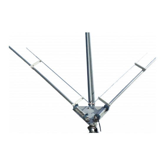
- Page 2 When both half-elements are ready, prepare the center plate and assemble all the parts as in the photo. The two half-dipoles lower ends must protrude from the insulator of 2.5 cm (1inch). The terminals of the airpin coil, must enter on the bolts head without strain or deformation and should be secured with its own washer and nut.
- Page 3 After completing the tune-up, check the tightness of all nuts. If the V dipole is installed above a HF yagi, it is preferable that it is installed parallel to the yagi boom and at a vertical distance of at least 1,5-2m. If installed alone it is preferable that at least 5m from the ground / roof / floor.
- Page 4 Kit 6m (optional) The 6m kit must be installed as in the photo below. For improvements and technical - production, specifications and design are subject to change, without affecting the final pourpose of the product. WARNING!!! Do not install this antenna near electric power lines or other sources of energy, even in the event of accidental contact, could kill or seriously hurt you.
Need help?
Do you have a question about the PST-1524TV and is the answer not in the manual?
Questions and answers