Table of Contents
Advertisement
www.keyestudio.com
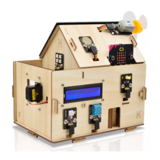
Smart Home Kit for Micro:bit
Smart Home Kit for Micro:bit ..................................................................................... 1
1.Introduction: .............................................................................................................. 3
2.Description: ................................................................................................................ 4
3.Kit List: ......................................................................................................................... 5
4. Preparations: ............................................................................................................. 10
4.1 Background Information about Micro:bit .............................................. 10
( 1 )What is Micro:bit? ................................................................................. 10
( 2 )Layout ...................................................................................................... 11
( 3 ) Pinout ...................................................................................................... 13
( 4 )Notes for the application of Micro:bit main board .................... 14
4.2.Install Micro:bit driver .................................................................................. 16
5.Getting Started with Micro:bit .............................................................................. 16
5.1 Write code and program ............................................................................ 17
5.2.Makecode: .................................................................................................... 28
5.3 Quick Download ............................................................................................ 29
5.4.Makecode extension library: ...................................................................... 37
5.4.Resources and test code ............................................................................. 46
5.5.Input test code ............................................................................................... 47
Contents
1
Advertisement
Table of Contents

Summary of Contents for Keyestudio KS4028
-
Page 1: Table Of Contents
Smart Home Kit for Micro:bit Contents Smart Home Kit for Micro:bit ..................1 1.Introduction: ......................3 2.Description: ........................ 4 3.Kit List: ......................... 5 4. Preparations: ......................10 4.1 Background Information about Micro:bit ..........10 ( 1 )What is Micro:bit? ................. 10 ( 2 )Layout ...................... - Page 2 5.6. Install CoolTerm: ..................52 6.Install the Smart Home ................... 55 7. Project: ........................109 Project 1: Heartbeat ..................109 Project 2: Light A Single LED ................112 Project 3: LED Dot Matrix ................117 Project 4: Programmable Buttons ..............121 Project 5: Temperature Detection ..............
-
Page 3: Introduction
Project 6: Adjust angles of servo ..............282 Project 7: 130 Motor ..................288 Project 8:Lithium Battery Power Module ..........298 Project 9:1602 LCD ..................302 Project 10:Steam Sensor ................310 Project 11:Rains Alarm .................. 317 Project 12:Analog Gas(MQ-2)Sensor ..........322 Project 13:Gas Leakage Detector ............... -
Page 4: Description
, utility and environmental consciousness. 2.Description: Launched by Keyestudio, this smart home kit is based on the open-source hardware of Micro:bit and designed for those who dream of living a more comfortable life with the help of technologies. -
Page 5: Kit List
By the way, it supports powering by solar energy or via USB cable. This tutorial will guide you to make and control the smart home kit by the code written in the online graphical programming platform Makecode. In this process, not only can you enhance your ability to make stuffs but also learn the skills of programming. - Page 6 Micro:bit Main Board Keyestudio Micro:bit Expansion Board with IO Port Wooden Board Acrylic Board 6812 RGB Module Analog Gas Sensor 130 Motor Module Steam Sensor...
- Page 7 DHT11 Temperature and Humidity Sensor PIR Motion Sensor Yellow LED Module Rechargeable Lithium Battery Power Module with Solar and USB Ports Battery Holder 14 Micro:bit Solar Energy Panel Servo 16 I2C 1602 LCD Module Rocker Switch...
- Page 8 15cm 3Pin F-F DuPont Wire 20cm 3Pin F-F DuPont Wire 20cm F-F DuPont Wire 20cm 4Pin F-F DuPont Wire 200mm 2Pin DuPont Wire M2*8MM Round-head Screw M1.4*6MM Round-head Self-tapping Screw M3 Nickel-plated Self-locking Nut M4*8MM Round-head Screw M3*6MM Round-head Screw...
- Page 9 Round-head Screw M2*12MM Round-head Screw 30 M4 Nickel-plated Nut 31 M3 Nickel-plated Nut 32 M2 Nickel-plated Nut M3*8MM Round-head Screw Wrench 3.0*40MM Screwdriver Red-Black 2.0*40MM Screwdriver Purple-Black 37 M3*45MM Dual-pass Copper Pillar USB Cable AM/MK5P(micro) Black OD:3.5 L=1M...
-
Page 10: Preparations
F5 Blue to Blue LED 18650 Battery(Not Included) 4. Preparations: 4.1 Background Information about Micro:bit ( 1 )What is Micro:bit? Micro:bit is an open source hardware platform based on the ARM architecture launched by British Broadcasting Corporation (BBC) together with ARM, Barclays, element14, Microsoft and other institutions. -
Page 11: 2 )Layout
Moreover, this board has a sleeping mode to lower power consumption of batteries and it can be entered if users long press the Reset & Power button on the back of it. It is capable of reading the data of sensors, controlling servos and RGB lights and attaching with a shield so as to connect with various sensors. - Page 12 For the Micro: Bit main board, pressing the Reset & Power button, it will reset the board and rerun the program.If you hold it tight, the red LED will slowly get darker.When the power indicator flickers into darkness, releasing the button and your Micro: Bit board will enter sleep mode for power saving .This will make the battery more durable.
-
Page 13: 3 ) Pinout
( 3 ) Pinout... -
Page 14: 4 )Notes For The Application Of Micro:bit Main Board
The functions of pins: P0,P1,P2,P3,P4,P5,P6,P7,P8,P9,P10,P11,P12, GPIO P13,P14,P15,P16,P19,P20 ADC/DAC P0,P1,P2,P3,P4,P10 P19(SCL),P20(SDA) P13(SCK),P14(MISO),P15(MOSI) PWM(used P0,P1,P2,P3,P4,P10 frequently) PWM(not P5、P6、P7、P8、P9、P11、P12、P13、P14、P15、P16、P19、 frequently used) P3(LED Col3),P4(LED Col1),P5(Button A),P6(LED Col4), Occupied P7(LED Col2),P10(LED Col5),P11(Button B) Browse the official website for more details: https://tech.microbit.org/hardware/edgeconnector/ https://microbit.org/guide/hardware/pins/ ( 4 )Notes for the application of Micro:bit main board a. - Page 15 Its IO port is very weak in driving since it can merely handle current less than 300mA. Therefore, do not connect it with devices operating in large current, such as servo MG995 and DC motor or it will get burnt.
-
Page 16: Install Micro:bit Driver
Forbid to operate it on metal products to avoid short circuit. To put it simple, Micro:bit V2 main board is like a microcomputer which has made programming at our fingertips and enhanced digital innovation. And as for programming environment, BBC provides a website: https://microbit.org/code/, which has a graphical MakeCode program easy... -
Page 17: Write Code And Program
5.1 Write code and program This chapter describes how to write program and load the program to the Micro: Bit main board V2. You are recommended to browse the official website of Micro:bit for more details, and the link is attached below: https://microbit.org/guide/quick/... - Page 18 Secondly, if the red LED on the back of the board is on, that means the board is powered. When your computer communicates with the main board via the USB cable, the yellow LED on it will flashes. For example, it will flicker when you burn a “hex”file.
- Page 19 Step 2: write programs View the link https://makecode.microbit.org/ in your browser; Click ‘New Project’; The dialog box‘Create a Project’ appears, fill it with ‘heartbeat’and click ‘Create √’to edit. (If you are running Windows 10 system, it is also viable to edit on the APP MakeCode for micro:bit , which is exactly like editing in the website.
- Page 20 www.keyestudio.com...
- Page 21 Write a set of micro:bit code. You can drag some modules in the Blocks to the editing area and then run your program in Simulator of MakeCode editor as shown in the picture below which demonstrates how to edit ‘heartbeat’...
- Page 22 Click the arrow behind “JS JavaScript”to choose between“JavaScript” or “Python”and you will find the corresponding program in JavaScript language or Python language as shown below:...
- Page 23 Step 3: download code If your computer is Windows 10 and you have downloaded the APP MakeCode for micro:bit to write program, what you will have to do to download the program to your Micro: Bit main board is merely clicking the ‘Download’...
- Page 24 USB driver. If you are running Windows system, you can also right-click and select ‘Send to → MICROBIT(E:) ‘to copy the hex file to the Micro: Bit main board.
- Page 25 You can also directly drag the "hex" file onto the MICROBIT (E:) disk.
- Page 26 During the process of copying the downloaded hex file to the Micro: bit main board, the yellow signal light on the back side of the board flashes. When the copy is completed, the yellow signal light will stop flashing and remain on.
- Page 27 Power via USB cable Power via external power (3V) Caution: When you programs each time, the driver of Micro: bit will automatically eject and return and your hexadecimal files will disappear . And the board can only have access to hexadecimal files (hex) and save no other files.
-
Page 28: Makecode
5.2.Makecode: Browse https://makecode.microbit.org/ and enter Makecode online editor or open the APP MakeCode for micro:bit of Windows 10. Click“New Project”, and input“heartbeat”, then click “create √”to enter Makecode editor, as shown below:... -
Page 29: Quick Download
Code editing Blocks area “+” zoom in “-” zoom out Download Return project Save Undo 销 There are blocks“on start”and“forever”in the code editing area. When the power is plugged or reset,“on start”means that the code in the block only executes once, while “ forever ” implies that the code runs cyclically. - Page 30 While it is a little more trickier if you are using a browser to enter Makecode. However, if you use Google Chrome, suitable for Linux,macOS and Windows 10, the process can be quicker too. We use the webUSB function of Chrome to allow the internet page to access the hardware device connected USB.
- Page 31 Click“Next”;...
- Page 32 Click another“Next”;...
- Page 33 Then select the corresponding device and click“Connect”. If no devices shows up for selection, please refer to: https://makecode.microbit.org/device/usb/webusb/troubleshoot updating firmware Micro:bit: https://microbit.org/guide/firmware/ . If the links are too troublesome for you , then you can also turn to our...
- Page 34 Click“Done”to finish the pairing.
- Page 35 www.keyestudio.com...
- Page 36 Download program: After the pairing, click “download”to directly download the program to the board. If it is successfully downloaded, the icon will shift to...
-
Page 37: Makecode Extension Library
5.4.Makecode extension library: For your convenience, we have made a makecode extension library for this smart home kit. Add smart home extension library: Please follow the following steps to add extension files: Open Makecode to enter a certain project→click the gear-shaped icon(for... - Page 38 Or click”Advanced”to select “Extensions”as shown below:...
- Page 39 Input the link https://github.com/keyestudio2019/ks_IoT to search; Tap the searching result “IoT_keyestudio” to download and install it; This process may take a few seconds.
- Page 40 After the installation, you can find the extension files DHT11/DHT22 and I2C_LCD1602 on the left side. And extension file Neopixel is also installed.
- Page 41 www.keyestudio.com...
- Page 42 www.keyestudio.com...
- Page 43 Note: the extension files added are only available for this project. Therefore, when you create a new IoT_keyestudio project, you will need to add these extension files again. Update or delete the IoT_keyestudio extension files: Please follow the following steps to update or delete extension files:...
- Page 44 Click the “Explorer”on the left side:...
- Page 45 You can find these added files in the list; Click the dustbin icon beside the file to delete the corresponding file; Tap the refresh icon to update the corresponding IoT_keyestudio extension file.
-
Page 46: Resources And Test Code
5.4.Resources and test code We also provide a link:https://fs.keyestudio.com/KS4027-4028 containing the information of the product from relevant tools to test codes, tutorials and troubleshooting methods as well, as shown in the figure below:... -
Page 47: Input Test Code
5.5.Input test code We provide hexadecimal code files (project files) for each project. The file contains all the contents of the project and can be imported directly, or you can manually drag the code blocks to complete the program for each project. - Page 48 Click“Import File”;...
- Page 49 Select“../Makecode Code/Project 1_ Heart beat/Project 1_ Heart beat.hex” Then click “Go ahead”.
- Page 50 In addition to importing the test code file provided into the Makecode compiler above, you can also drag the the test code file provided into the code editing area of the Makecode compiler, as shown in the figure below:...
- Page 51 Note: if your computer system is Windows7 or 8 instead of Windows 10, the pairing cannot be done via Google Chrome. Therefore, digital signal or analog signal of sensors and modules cannot be shown on the serial port simulator. However, you need to read the corresponding digital signal or analog signal.So what can we do? You can use the CoolTerm software to...
-
Page 52: Install Coolterm
5.6. Install CoolTerm: CoolTerm program is used to read the data on serial port. Download CoolTerm program: https://freeware.the-meiers.org/ After the download, we need to install CoolTerm program file, below is PC Window system taken as an example. (1) Choose“win”to download the zip file of CoolTerm (2) Unzip file and open it. - Page 53 Double-click (please make sure that the driver of Micro:bit is installed and the main board is connected with the computer.) The functions of each button on the Toolbar are listed below:...
- Page 54 Open up a new Terminal Open a saved Connection Save the current Connection to disk Open the Serial Connection Close the Serial Connection Clear the Received Data Open the Connection Options Dialog Display the Terminal Data in Hexadecimal Format...
-
Page 55: Install The Smart Home
6.Install the Smart Home Part 1 Component s Needed... - Page 56 Installation Diagram Prototype Part 2...
- Page 57 Component s Needed Installation Diagram...
- Page 58 Prototype Part 3 Component s Needed...
- Page 59 Installation Diagram...
- Page 60 Prototype Adjust Wiring: angle of the Connect the main board with Micro:bit servo the shield with Expansion Servo controlling computer via USB cable; Board windows to Plug them up; Brown Turn the slide switch on the ° Wire board to the “ON”end, and the rocker switch to the “1”...
- Page 61 Example code: After uploading the example code to Micro:bit, the angle of the servo is set to 0°. Part 4...
- Page 62 Component Needed (peel sticker gear-shaped Acrylic board first) Installation Diagram...
- Page 63 Prototype Part 5 Component s Needed...
- Page 64 Installation Diagram Prototype...
- Page 65 Part 6 Component s Needed (peel sticker Acrylic board first)
- Page 66 Installation Diagram (The gears of the N Board should properly jointed with wooden gear and do self-locking nut tight; after installation, door closed.)...
- Page 67 Prototype Part 7...
- Page 68 Component s Needed Installation Diagram...
- Page 69 Prototype Part 8...
- Page 70 Component s Needed Installation Diagram...
- Page 71 Prototype Part 9 Component s Needed...
- Page 72 Installation Diagram Prototype Part 10...
- Page 73 Component s Needed...
- Page 74 Installation Diagram (stick solar panel along right side of line marked the picture; pull wires on the panel from hole in the middle.) Prototype Part 11...
- Page 75 Component s Needed Installation Diagram...
- Page 76 Prototype Part 12 Component s Needed...
- Page 77 Installation Diagram Prototype Part 13...
- Page 78 Component s Needed Installation Diagram...
- Page 79 Prototype Part 14 Component s Needed...
- Page 80 Installation Diagram Prototype Part 15...
- Page 81 Component s Needed Installation Diagram...
- Page 82 Prototype Part 16 Component s Needed...
- Page 83 Installation Diagram Prototype Part 17...
- Page 84 Component Needed...
- Page 85 Installation Diagram Prototype...
- Page 86 Part 18 Component s Needed...
- Page 87 Installation Diagram Prototype Part 19...
- Page 88 Component s Needed (peel sticker Acrylic board first)
- Page 89 Installation Diagram...
- Page 90 Prototype Part 20 Component s Needed...
- Page 91 Installation Diagram...
- Page 92 Prototype Part 21...
- Page 93 Component s Needed...
- Page 94 Installation Diagram...
- Page 95 Prototype Start Wiring...
- Page 96 (plug its jack to the BAT end of the rechargeabl power module)
- Page 97 LED wiring of the RGB module...
- Page 98 PIR motion sensor wiring 1602LCD...
- Page 99 sensor...
- Page 100 window...
- Page 101 (Connect shield with attach red wire to V black one to G.)...
- Page 102 panel...
- Page 103 (Please pay attention to the pins and connection cannot reversed.)
- Page 104 (Connect to the P0 of 3.3V or the analog value read.) Mount the Roof...
- Page 105 Component s Needed Installation Diagram...
- Page 106 Prototype Installation Diagram...
- Page 107 Prototype...
- Page 108 Install Micro:bit main board Prototype...
-
Page 109: Project
7. Project: Project 1: Heartbeat (1) Project Introduction This project is easy to conduct with a micro:bit main board, a Micro USB cable and a computer. The micro:bit LED dot matrix will display a relatively big heart-shaped pattern and then a smaller one. This alternative change of this pattern is like heart beating. - Page 110 Micro:bit main board *1 USB cable*1 (3)Connection Diagram: Attach the Micro:bit main board to your computer via the USB cable. (4)Test Code: The route to get test codes(How to load?) File Type Path File Name Hex file KS4027 folder/Makecode Project 1:Heart...
- Page 111 Firstly, you can view this link https://makecode.micro:bit.org/reference find more information about micro: bit blocks. Then this link https://makecode.micro:bit.org/ can help you write code. Command blocks can be found on the right: Make combinations of these blocks: Click the arrow behind“JS JavaScript”to select between“JavaScript”and...
-
Page 112: Project 2: Light A Single Led
“Python”to show the code in JavaScript language or Python language: (5)Test Results: After uploading test code to micro:bit main board and keeping the connection with the computer to power the main board, the LED dot matrix shows pattern“ ”and then“... - Page 113 (1) Project Introduction In this project, we intend to control a certain LED of the micro:bit main board to shine. (2)Components Needed: Micro:bit main board *1 USB cable*1 (3)Connection Diagram: Attach the Micro:bit main board to your computer via the USB cable.
- Page 114 (4)Introduction of components: The LED dot matrix consists of 25 LEDs arranged in a 5 by 5 square. In order to locate these LEDs quickly, as the figure shown below, we can regarded this matrix as a coordinate system and create two aces by marking those in rows from 0 to 4 from top to bottom, and the ones in columns from 0 to 4 from the left to the right.
- Page 115 KS4027 folder/Makecode Project 2:Light A file Tutorial/Makecode Single LED.hex Code/Project Code/Project 2: Light A Single LED You can also drag blocks to form code. Command blocks can be found on the right as shown below:...
- Page 116 Make combinations of these blocks:...
-
Page 117: Project 3: Led Dot Matrix
(6)Test Result After uploading test code to micro:bit main board and powering the main board via the USB cable, the LED in (1,0) lights up for 1s and the one in (3,4) shines for 1s and repeat this sequence. - Page 118 (2)Components Needed: Micro:bit main USB cable*1 board *1 (3)Connection Diagram: Attach the Micro:bit main board to your computer via the Micro USB cable. (4)Test Code: The route to get test codes(How to load?) File Route File Name Type...
- Page 119 Hex file KS4027 folder/Makecode Project 3:LED Dot Tutorial/Makecode Code/Project Matrix.hex Code/Project 3:LED Dot Matrix You can also drag blocks to form code. Command blocks can be found on the right as shown below:...
- Page 120 Make combinations of these blocks:...
-
Page 121: Project 4: Programmable Buttons
(5)Test Result: After uploading test code to micro:bit main board and powering the main board via the USB cable, we find that the 5*5 dot matrix start to show numbers 1,2,3,4 and 5, and then it alternatively shows a downward arrow , word “Hello”, a heart pattern... - Page 122 A and B), and the one on the other side is a reset button. By pressing the two programmable buttons can input three different signals. We can press button A or B alone or press them together and the LED dot matrix shows A,B and AB respectively.
- Page 123 (4)Test Code 1: The route to get test codes(How to load?) File Route File Name Type Hex file KS4027 folder/Makecode Project 4:Code-1.hex Tutorial/Makecode Code/Project Code/Project 4:Programmable Buttons You can also drag blocks to form code. Command blocks can be found on the right as shown below:...
- Page 124 Make combinations of these blocks: (5)Test Result 1: After uploading test code to micro:bit main board and powering the main board via the USB cable, the 5*5 LED dot matrix shows A if button A is pressed and then released, B if button B pressed and released, and AB if button A and B pressed together and then released.
- Page 125 File Route File Name Type Hex file KS4027 folder/Makecode Project 4:Code-2.hex Tutorial/Makecode Code/Project Code/Project 4:Programmable Buttons You can also drag blocks to form code. Command blocks can be found on the right as shown below:...
- Page 126 www.keyestudio.com...
- Page 127 Make combinations of these blocks:...
-
Page 128: Project 5: Temperature Detection
(7)Test Result 2: After uploading test code to micro:bit main board and powering the main board via the USB cable, when the button A is pressed, the LEDs turning red increase while when the button B pressed, the LEDs turning red reduce. - Page 129 Micro:bit main USB cable*1 board *1 (3)Connection Diagram: Attach the Micro:bit main board to your computer via the USB cable. (4)Test Code 1: The route to get test codes(How to load?) File Route File Name Type Hex file KS4027 folder/Makecode Project 5:Code-1.hex...
- Page 130 You can also drag blocks to form code. Command blocks can be found on the right as shown below:...
- Page 131 www.keyestudio.com...
- Page 132 Make combinations of these blocks:...
- Page 133 (5)Test Result 1: After uploading test code 1 to micro:bit main board, powering the main board via the USB cable, and clicking“Show console Device”, the data of temperature shows in the serial monitor page as shown below.
- Page 134 When you touch the processor nNRF52833 on the board for a while, its temperature will rise gradually and the CoolTerm serial monitor will show the change of temperature in the current environment, as shown in the figures below :...
- Page 135 If you're running Windows 7 or 8 instead of Windows 10, via Google Chrome won't be able to match devices. You'll need to use the CoolTerm serial monitor software to read data. You could open CoolTerm software, click Options, select SerialPort, set...
- Page 136 :...
- Page 137 www.keyestudio.com...
- Page 138 www.keyestudio.com...
- Page 139 (6)Test Code 2: The route to get test codes(How to load?) File Route File Name Type Hex file KS4027 folder/Makecode Project 5: Tutorial/Makecode Code-2.hex Code/Project Code/Project 5: Temperature Detection...
- Page 140 You can also drag blocks to form code. Command blocks can be found on the right as shown below:...
- Page 141 Make combinations of these blocks: (Please note that the value 35 in the statement below can be changed according to real situation.)
-
Page 142: Project 6: Geomagnetic Sensor
(7)Test Result 2: After uploading the code 2 to the board, when the ambient temperature is less than 35 ℃ , the 5*5 LED dot matrix shows . When the temperature is equivalent to or greater than 35 ℃ , the pattern appears. - Page 143 Micro: Bit main board uses LSM303AGR geomagnetic sensor, which supports four modes namely 100 kHz,400 kHz,1 MHz and 3.4 MHz and the dynamic range of magnetic field is ±50 gauss. In the board, the magnetometer module is used in both magnetic detection and compass.
- Page 144 Micro:bit main USB cable*1 board *1 (3)Connection Diagram: Attach the Micro:bit main board to your computer via the USB cable. (4)Test Code 1: The route to get test codes(How to load?) File Route File Name Type KS4027 folder/Makecode Project 6:...
- Page 145 Code/Project Code/Project 6: Geomagnetic Sensor You can also drag blocks to form code. Command blocks can be found on the right as shown below:...
- Page 146 Make combinations of these blocks: Note: it is imperative to calibrate the Micro:bit board for different geomagnetic fields existing in different places. And the system will make an automatic requirement if it is used for the first time. (5)Test Result1:...
- Page 147 After that, a smile pattern appears, which implies the calibration is done. When the calibration process is completed, pressing the button A will make the magnetometer reading display directly on the screen. And the direction north, east, south and west correspond to 0°, 90°, 180° and 270°...
- Page 148 Tutorial/Makecode Code-2.hex Tutorial/Project Code/Project 6: Geomagnetic Sensor This module can keep reading data to determine direction, so does point to the current magnetic North Pole by arrow.
- Page 149 For the above picture, the arrow pointing to the upper right when the value ranges from 292.5 to 337.5. Because 0.5 can’t be input in the code, the values we get are 293 and 338. Then add other statements to make a set of complete code.
- Page 150 www.keyestudio.com...
- Page 151 www.keyestudio.com...
- Page 152 Make combinations of these blocks:...
- Page 153 www.keyestudio.com...
- Page 154 www.keyestudio.com...
- Page 155 (7)Test Result 2: Upload code 2 and plug micro:bit into power. After calibration, tilt micro:bit board, and the LED dot matrix displays the direction signs.
-
Page 156: Project 7: Accelerometer
Project 7: Accelerometer (1) Project Introduction The Micro: Bit main board V2 has a built-in LSM303AGR gravity acceleration sensor, also known as accelerometer, with a resolution of 8/10/12 bits. The code section sets the range to 1g, 2g, 4g, and 8g. - Page 157 (3)Connection Diagram: Attach the Micro:bit main board to your computer via the USB cable. (4)Test Code 1: The route to get test codes(How to load?) File Route File Name Type KS4027 folder/Makecode Project 7:Code-1.hex file Tutorial/Makecode Code/Project Code/Project 7:...
- Page 158 Make combinations of these blocks: (5)Test Result 1:...
- Page 159 After uploading the test code 1 to micro:bit main board and powering the board via the USB cable, if we shake the Micro: Bit main board, no matter at any direction, the LED dot matrix displays the digit “1”.
- Page 160 When it is placed still on the desk, showing its back side, the number 5 exhibits. When the board is tilted to the left , the LED dot matrix shows the number 6 as shown below. When the board is tilted to the right , the LED dot matrix displays the number 7 as shown below:...
- Page 161 Attention: if you’ d like to try this function, you can also set the acceleration to 3g, 6g or 8g. But still ,we do not recommend. (6) Test Code 2:...
- Page 162 Command blocks:...
- Page 163 Make combinations of these blocks:...
- Page 164 (7)Test Result 2: Upload test code to micro:bit main board, power the main board via the USB cable, and click “Show console Device”.
- Page 165 After referring to the MMA8653FC data manual and the hardware schematic diagram of the Micro: Bit main board, the accelerometer coordinate of the Micro: Bit are shown in the figure below: The following interface shows the decomposition value of acceleration in X...
- Page 166 (acceleration synthesis of gravity and other external forces). If you're running Windows 7 or 8 instead of Windows 10, via Google Chrome won't be able to match devices. You'll need to use the CoolTerm serial monitor software to read data.
-
Page 167: Project 8: Light Brightness Detection
Project 8: Light Brightness Detection... - Page 168 (1) Project Introduction In this project, we focus on the light detection function of the Micro: Bit main board V2. It is achieved by the LED dot matrix. And it can be viewed as a photosensor. (2)Components Needed: Micro:bit main...
- Page 169 Attach the Micro:bit main board to your computer via the USB cable. (4)Test Code: The route to get test codes(How to load?) File Route File Name Type Hex file KS4027 folder/Makecode Project 8:Light Tutorial/Makecode Code/Project Brightness Code/Project 8:Light Brightness Detection.hex...
- Page 170 www.keyestudio.com...
- Page 171 Make combinations of these blocks:...
- Page 172 (5)Test Result: Upload the test code to micro:bit main board, power the board via the USB cable and click“Show console Device”.
- Page 173 When the LED dot matrix is covered by hand, the light intensity showed is approximately 0; when the LED dot matrix is exposed to light,the light intensity displayed gets stronger with the light as shown below:...
- Page 174 The 20 in the code is an arbitrary value of light intensity. If the current light level is less than or equal to 20, the icon moon will appear on the LED dot matrix. If it's bigger than 20, the sun will appear.
- Page 175 You could open CoolTerm software, click Options, select SerialPort, set COM port and baud rate to 115200 (after testing, the baud rate of USB SerialPort communication on Micro: Bit main board is 115200), click OK, Connect.
-
Page 176: Project 9: Speaker
Project 9: Speaker (1) Project Introduction Micro: Bit main board has an built-in speaker, which makes adding sound to the programs easier. With a speaker, all Micro:bit board can be used to create sound-related projects. But the new version, that’s the version 2 is able to make the speaker utter giggles, greetings and yawning and sound sad. - Page 177 *1 (3)Connection Diagram: Attach the Micro:bit main board to your computer via the USB cable. (4)Test Code 1: The route to get test codes(How to load?) File Type Route File Name Hex file KS4027 folder/Makecode Project 9:Code-1.hex Tutorial/Makecode Code/Project Code/Project 9: Speaker You can also drag blocks to form code.
- Page 178 Make combinations of these blocks:...
- Page 179 (5)Test Result 1: After uploading the Test Code 1 to micro:bit main board and powering the board via the USB cable, the speaker utters sound and the LED dot matrix shows the logo of music. (6)Test Code 2: The route to get test codes(How to...
- Page 180 File Route File Name Type Hex file KS4027 folder/Makecode Project 9: Tutorial/Makecode Code-2.hex Code/Project Code/Project 9: Speaker You can also drag blocks to form code. Command blocks can be found on the right as shown below:...
- Page 181 Make combinations of these blocks:...
- Page 182 www.keyestudio.com...
- Page 183 www.keyestudio.com...
- Page 184 www.keyestudio.com...
- Page 185 www.keyestudio.com...
- Page 186 www.keyestudio.com...
- Page 187 The musical score of Ode to Joy is attached below:...
- Page 188 Find more information about musical notations via this link: https://en.wikipedia.org/wiki/Numbered_musical_notation (7) Test Result 2: After uploading the Test Code 2 to micro:bit main board and powering the board via the USB cable, the speaker on built-in the Micro:bit board plays...
-
Page 189: Project 10: Touch-Sensitive Logo
Project 10: Touch-sensitive Logo (1) Project Introduction The Micro: Bit main board is equipped with a golden touch-sensitive logo, which can act as an input component and function like an extra button. It contains a capacitive touch sensor that senses small changes in the electric field when pressed (or touched), just like your phone or tablet screen do.When you press it , you can activate the program. - Page 190 (4)Test Code: The route to get test codes(How to load?) File Route File Name Type KS4027 folder/Makecode Project 10: file Tutorial/Makecode Touch-sensitive Code/Project Code/Project 10: Logo.hex Touch-sensitive Logo You can also drag blocks to form code. Command blocks can be found on the right as shown below:...
- Page 191 www.keyestudio.com...
- Page 192 Make combinations of these blocks:...
-
Page 193: Project 11: Microphone
(5)Test Results: After uploading the test code to micro:bit main board and powering the board via the USB cable, the LED dot matrix exhibits the heart pattern when the touch-sensitive logo is pressed or touched and displays digit when the logo is released. The longer it is pressed, the bigger the number is when it is released. - Page 194 The Micro: Bit main board is built with a microphone which can test the volume of ambient environment. When you clap, the microphone LED indicator turns on. Since it can measure the intensity of sound, you can make a noise scale or disco lighting changing with music. The microphone is placed on the opposite side of the microphone LED indicator and in proximity with holes that lets sound pass.When the board detects sound,...
- Page 195 (4)Test Code 1: The route to get test codes(How to load?) File Route File Name Type Hex file KS4027 folder/Makecode Project 11: Tutorial/Makecode Code/Project Code-1.hex Code/Project 11:Microphone You can also drag blocks to form code. Command blocks can be found on the right as shown below:...
- Page 196 (5)Test Result 1: After uploading test code to micro:bit main board and powering the board via the USB cable, the LED dot matrix displays pattern when you clap “ ” and pattern when it is quiet around. (6)Test Code 2: The route to get test codes(How to...
- Page 197 www.keyestudio.com...
- Page 198 Make combinations of these blocks:...
- Page 199 (2)Test Result 2: Upload test code to micro:bit main board, power the board via the USB cable and click “Show console Device”as shown below:...
- Page 200 When the sound is louder around, the sound value shows in the serial port is bigger as shown below:...
-
Page 201: Project 12: Play Music
What’s more, when the button A is pressed, the LED dot matrix displays the value of the biggest volume( please note that the biggest volume can be reset via the Reset button on the other side of the board ) while when clapping, the LED dot matrix shows the pattern of the sound. - Page 202 In the previous projects, we have learned about the touch-sensitive logo and the speaker respectively. In the project, we will combine these two components to play music. That’s the logo will be applied to control the speaker to sing songs.
- Page 203 File Route File Name Type KS4027 folder/Makecode Project 12:Play Music.hex file Tutorial/Makecode Code/Project Code/Project 12: Play Music You can also drag blocks to form code. Command blocks can be found on the right as shown below:...
- Page 204 Make combinations of these blocks: (5)Test Results: After uploading test code to micro:bit main board and powering the board via the USB cable, the speaker plays the song Happy Birthday to You when...
-
Page 205: Project 13: Dodge Bullets
Project 13: Dodge Bullets (1) Project Introduction In the previous projects, we have learned about the two programmable buttons, button A and B, and the LED dot matrix respectively. In this one, we will combine them to design a game- Dodge Bullets. - Page 206 Attach the Micro:bit main board to your computer via the USB cable. (4)Game Rule1 There are two bullets (marked as G1 and G2)falling from the LED dot matrix and a role G on the bottom of the matrix. Button A and B can be used to control the movement of the role to dodge bullets.
- Page 207 You can also drag blocks to form code. Command blocks can be found on the right as shown below:...
- Page 208 www.keyestudio.com...
- Page 209 www.keyestudio.com...
- Page 210 Make combinations of these blocks:...
- Page 211 www.keyestudio.com...
- Page 212 (6)Test Result 1: The game begins when the code is uploaded to the main board. The bullets G1 and G2 fall off and the role G is controlled by Button A and B to shun them. If the role fail to avert the attacks, the game is over.
- Page 213 Built on the rule1, a new rule is added that one will get score in this game. And with the accumulation of the score, the difficulty of this game mounts. The detail of rule2 is that when the role G dodge a bullet, 1 score is gained and that the game stops when it is hit and the game is over after the display of the scores.
- Page 214 www.keyestudio.com...
- Page 215 www.keyestudio.com...
- Page 216 www.keyestudio.com...
- Page 217 Make combinations of these blocks:...
- Page 218 www.keyestudio.com...
- Page 219 (9)Test Result 2: The game begins when the code is uploaded to the main board. The bullets G1 and G2 fall off and the role G is controlled by Button A and B to shun them. 1 score will be tallied for each successful dodging. If the role fail to avert the attacks, the game halts and it is over after the exhibition of the scores gained.
- Page 220 Project 14: Bluetooth Wireless Communication (1)Project Introduction The Micro: Bit main board comes with a nRF52833 processor (with a built-in BLE(Bluetooth Low Energy) device Bluetooth 5.1 ) and a 2.4GHz antenna for Bluetooth wireless communication and 2.4GHz wireless communication. With the help of them, the board is able to communicate with a variety of Bluetooth devices, including smart phones and tablets.
- Page 221 (2)Components Needed: Micro:bit main Micro Smart Phone/iPad*1 board *1 cable*1 (3)Connection Diagram: Attach the Micro:bit main board to your computer via the Micro USB cable.。 (4)Procedures: Step 1: Apple devices, enter this link https://www.microbit.org/get-started/user-guide/ble-ios/ with your computer first, and then click “Download pairing HEX file”to download the Micro: Bit firmware to a folder or desk, and upload the downloaded firmware to the Micro: Bit main board.
- Page 222 (Only Apple devices should follow this step. Not needed for Android systems.)
- Page 223 www.keyestudio.com...
- Page 224 Step 2: Search “micro bit”in your App Store to download the APP micro:bit. Step 3: Connect your Apple device with Micro: Bit main board : Firstly, turn on the Bluetooth of your Apple device and click icon to open the APP micro:bit and select item “Choose micro:bit”to start...
- Page 225 Secondly, click“Pair a new micro:bit”;...
- Page 226 Following the instructions to press button A and B at the same time(do not release them until you are told to) and press Reset & Power button for a few seconds. Release the Reset & Power button, you will see a password pattern shows...
- Page 227 www.keyestudio.com...
- Page 228 Set the password pattern on your Apple device as the same pattern showed on the matrix and click “Next”.
- Page 229 Still click “Next”and a dialog box props up as shown below. Then click "Pair". A few seconds later, the match is done and the LED dot matrix displays the "√" pattern.
- Page 230 www.keyestudio.com...
- Page 231 www.keyestudio.com...
- Page 232 After the match with Bluetooth, write and upload code with the App. Click “Create Code” to enter the programming page and write code. Click and the box appears, and then select “Create √”.
- Page 233 www.keyestudio.com...
- Page 234 www.keyestudio.com...
- Page 235 Name the project as “1 “and click to save it.
- Page 236 Click the third item“Flash”to enter the uploading page. The default code program for uploading is the one saved just now and named "1" and then click the other "Flash" to upload the code program "1".
- Page 237 www.keyestudio.com...
- Page 238 www.keyestudio.com...
- Page 239 If the program “1”is uploaded successfully a few seconds later, the App will emerge as below and the LED dot matrix of the Micro: Bit main board will exhibit a heart pattern.
-
Page 240: Expansion Projects
8.Expansion Projects: The former 14 projects are the introduction of sensors and modules. The further lessons are challenging for new starters. Note: (G), marked on each sensor and module, is the negative pole and connected to “G”, ”-”or “GND”on the sensor shield or control board ;... -
Page 241: Project 1:Led Blinks
And you need to connect a power in case that power supply is weak. Project 1:LED Blinks (1)Project Introduction We’ve set up the micro:bit smart home. Now let’s get started from the most simple experiment---LED blink. - Page 242 The components will be damaged if LED is directly connected to the power supply. It’s essential that a certain resistor must be connected in series in the LED circuit.
- Page 243 (3)Test Code The route to get test codes(How to load?) Type Route File Name Hex file KS4027 folder/Makecode Project 1:LED Tutorial/Makecode Blinks.hex Code/Expansion Projects/Project 1: LED Blinks You can also drag blocks to form code. Command blocks can be found on the right as shown below:...
- Page 244 Make combinations of these blocks: Micro:bit Shield Yellow LED Module S(16)...
- Page 245 (4)Test Results: Upload the test code to the micro:bit,plug in power, dial the DIP switch to ON and press“1”on the rocket switch. The micro:bit will show smile expression, and a yellow LED will flash with an interval of 1000ms.
-
Page 246: Project 2:Breathing Led
Project 2:Breathing LED (1)Project Introduction In previous lesson, we control LED on and off and make it blink. In this project, we will control LED’s brightness through PWM simulating breathing effect. Similarly, you can change the step length and delay time in the code so as to demonstrate different breathing effects. - Page 247 Actually, it generates 25 pictures per second, which cannot be told by human eyes. Therefore, we mistake it as a continuous process. PWM works in the same way. To output different voltages, we need to control the ratio of 0 and 1. The more‘0’or ‘1’...
- Page 248 PWM is applied to light brightness adjustment, speed adjustment of motor and sound emitting. Parameters of PWM: pulse width (minimum / max) Pulse cycle (insertion of pulse frequency within 1 second)
- Page 249 Voltage level(0V-3V) There are commonly used PWM ports, namely P0, P1, P2, P3, P4 and P10. And there are other rarely used ports, namely P5, P6, P7, P8, P9, P11, P12, P13, P14, P15, P16, P19 and P20. In the experiment, we connect the port S of yellow LED Module to the port S (16) of the expansion board.
- Page 250 Display Yellow Color: (3) Test Code The route to get test codes(How to load?) Type Route File Name Hex file KS4027 folder/Makecode Project 2: Tutorial/Makecode Breathing LED.hex Code/Expansion Projects/Project Breathing You can also drag blocks to form code.
- Page 251 www.keyestudio.com...
- Page 252 Make combinations of these blocks: Micro:bit Expansion Board Yellow LED Module S(16)...
- Page 253 (4)Test Results: Upload the test code to the micro:bit,plug in power, dial the DIP switch to ON and press“1”on the rocket switch. The micro:bit will show a smile expression, and LED smoothly changes its brightness from light to dark and back to light, continuing to do so, which is similar to a lung breathing in and out.
-
Page 254: Project 3:6812 2X2 Full Color Rgb
Project 3:6812 2x2 Full Color RGB (1)Project Introduction 6812 2X2 full-color RGB module integrates the controlling circuit and the illuminating circuit. Each LED is the same as a 5050 LED lamp bead, and each component is a pixel point. The inner pixel point includes a amplify... - Page 255 Working 200mA Max Power: Voltage: 3.3-5V Working Current: Working ℃ Source of IC Type: 4 pcs/WS2811 Temperat ~+50℃ light: 5050 ure: Gray Illuminati 180° Illuminating Red, yellow, Scale: Color: blue,green and Angle: white (3)Add NeoPixel Library: Set code by the library, and click“Extensions”to add the library file.
- Page 256 Click the neoPixel library, then NeoPixel library is installed. You can view it in the blocks list.
- Page 257 (4)Test Code 1 The route to get test codes(How to load?) File Route File Name Type KS4027 folder/Makecode Project 3:Code-1.hex file Tutorial/Makecode Code/Expansion Projects/Project 6812 2x2Full-colorRGB You can also drag blocks to form code. Command blocks can be found on the right as shown below:...
- Page 258 Make combinations of these blocks: Micro:bit 6812 2x2 Full Color Expansion Board RGB Module S(14)...
- Page 259 (5)Test Result 1: Upload the Test Code 1to the micro:bit,plug in power, dial the DIP switch to ON and press“1”on the rocket switch. You will view the 6812 RGB...
- Page 260 (How to download? How to quick download?) (6)Test Code 2: The route to get test codes(How to load?) File Route File Name Type KS4027 folder/Makecode Project 3:Code-2.hex...
- Page 261 www.keyestudio.com...
- Page 262 Make combinations of these blocks:...
- Page 263 www.keyestudio.com...
- Page 264 www.keyestudio.com...
- Page 265 7.5. Test Result2: Upload the test code 2 to the micro:bit,plug in power, dial the DIP switch to ON and press“1”on the rocket switch. You can view four WS2812RGB lights light up,like a flowing light. (How to download? How to quick...
- Page 266 File Route File Name Type Hex file KS4027 folder/Makecode Project 3:Code-3.hex Tutorial/Makecode Code/Expansion Projects/Project 6812 2x2Full-colorRGB You can also drag blocks to form code. Command blocks can be found on the right as shown below:...
- Page 267 www.keyestudio.com...
- Page 268 Make combinations of these blocks:...
- Page 269 Upload the test code 3 to the micro:bit,plug in power, dial the DIP switch to ON and press“1”on the rocket switch. Then you will see 5 WS2812RGB lights light up with random colors, like a flowing light. (How to download? How to quick...
-
Page 270: Project 4:Pir Motion Sensor
Project 4:PIR Motion Sensor (1)Project Introduction The Pyroelectric infrared motion sensor can detect infrared signals from moving objects, and output switching signals. Applied to a variety of occasions, it can detect movement of human body. Conventional pyroelectric infrared sensors are much more bigger, with complex circuit and lower reliability. - Page 271 Working Voltage: DC 4.5-6.5V Max Working Current: 50MA Static Current: <50uA Control Port: Digital output (high level is 3.3V , low level is 0V) Control Signals: Digital signal 1/0 Working Temperature: -10 ~ 50 ℃ Max detection distance Sensing Angle:...
- Page 272 Note: 1. The maximum distance is 4 meters during testing. 2. In the test, open the white lens to check rectangular sensing part. When the long line of the sensing part is parallel to the ground, the distance is the best.
- Page 273 The route to get test codes(How to load?) File Route File Name Type Hex file KS4027 folder/Makecode Project 4:PIR Motion Tutorial/Makecode Sensor.hex Code/Expansion Projects/Project 4:PIR Motion Sensor You can also drag blocks to form code. Command blocks can be found on the right as shown below:...
- Page 274 www.keyestudio.com...
- Page 275 Make combinations of these blocks: Micro:bit Expansion PIR Motion Sensor Board S(15) (4)Test Results: Upload the test code to the micro:bit,plug in power, dial the DIP switch to ON and press“1”on the rocket switch. The micro:bit will show a smile image. Then click“Show console device”...
- Page 276 If PIR motion sensor detects someone nearby, the serial monitor will display “1” , and the indicator on the module will be off. If nobody is around, the serial monitor will show “0”, the indicator will be on. As shown below: If your computer system is Windows7/8 instead of Windows 10, the device can ’...
- Page 277 www.keyestudio.com...
-
Page 278: Project 5:Induction Lamp
Project 5:Induction Lamp (1)Project Introduction In the previous project experiment, we have mastered the working principle of the PIR motion sensor and its control method. In this project, we combine it with a yellow LED to control LED’s brightness... - Page 279 www.keyestudio.com...
- Page 280 Make combinations of these blocks: Micro:bit Micro:bit Yellow PIR Motion Expansion Expansion Sensor Board Board Module S(15) S(16)...
- Page 281 (3)Test Results: Upload the test code to the micro:bit, plug in power, dial the DIP switch to ON and press“1”on the rocket switch. The micro:bit will show a smile image. When the PIR motion sensor detects people, the yellow LED will be on;...
-
Page 282: Project 6: Adjust Angles Of Servo
Project 6: Adjust angles of servo (1) Project Introduction Servo motor is a position control rotary actuator. It mainly consists of a housing, a circuit board, a core-less motor, a gear and a position sensor. Its working principle is that the servo receives the signal sent by MCU or receiver and produces a reference signal with a period of 20ms and width of 1.5ms, then compares the acquired DC bias voltage to the voltage of the... - Page 283 The rotation angle of servo motor is controlled by regulating the duty cycle of PWM (Pulse-Width Modulation) signal. The standard cycle of PWM signal 20ms (50Hz). Theoretically, width distributed between 1ms-2ms, but in fact, it's between 0.5ms-2.5ms. The width corresponds the rotation angle from 0°...
- Page 284 2.5ms 180° 2.5ms high level+17.5mslow level (3) Servo: Working DC 4.8V 〜 Operational About 180 ° (500 → voltage: Angle: 2500μsec) Pulse width 500 → 2500 Size: 22.9*12.2*30mm range: μsec No-load 0.12±0.01 sec/60°(DC 4.8V) 0.1±0.01 sec/60° speed: (DC 6V)...
- Page 285 (4)Test Code: The route to get test codes(How to load?) File Route File Name Type Hex file KS4027 folder/Makecode Project 6:Adjust Tutorial/Makecode Code/Expansion angles of servo.hex Projects/Project 6: Adjust angles of servo You can also drag blocks to form code.
- Page 286 Make combinations of these blocks: Micro:bit Expansion Board Servo Brown S(8) Orange...
- Page 287 (5)Test Results: Upload the test code to the micro:bit, plug in power, dial the DIP switch to ON and press “ 1 ” on the rocket switch. The micro:bit will show smile expression, the servo will rotate 0°~45°~90°~135°~180°~0°,in loop way.
-
Page 288: Project 7: 130 Motor
Project 7: 130 Motor (1)Project Introduction 130 motor adopts the HR1124S chip which is applied to single-channel H-bridge drive chip in direct current motor. H-bridge driving part uses the PMOS and NMOS power tubes of low on-resistance. In addition, the HR1124S chip has the low standby and static current. - Page 289 Working 3.3-5V(DC) Max Current: 200mA (DC5V) Voltage: Max Power: Control port: Dual digital port (digital input) Working -10°C ~+50°C Environmental ROHS Temperature: Attribute:...
- Page 290 (3) Test Code 1:(high/low level control) The route to get test codes(How to load?) File Route File Name Type Hex file KS4027 folder/Makecode Project 7:Code-1.hex Tutorial/Makecode Code/Expansion Projects/Project 7:130 Motor You can also drag blocks to form code. Command blocks can be found on the right as shown below:...
- Page 291 Make combinations of these blocks: Micro:bit Expansion Board Motor S(13) S(12)...
- Page 292 Code Explanation: IN+ (digital port P12) IN-(digital port P13) high level(1) low level(0) Rotate clockwise...
- Page 293 IN+(digital portP12) IN-(digital port P13) low level(0) high level(1) Rotate anticlockwise IN+(digital portP12) IN-(digital port P13) low level(0) low level(0) Not rotating IN+(digital portP12) IN-(digital port P13) high level(1) high level(1) Not rotating...
- Page 294 4.Test Code 2:(PWM Speed control ) The route to get test codes(How to load?) File Route File Name Type KS4027 folder/Makecode Project 7: file Tutorial/Makecode Code-2.hex Code/Expansion Projects/Project 7: 130-Motor You can edit code blocks yourself:...
- Page 295 Make combinations of these blocks:...
- Page 296 Code Explanation: IN+(digital portP12) IN-(digital portP13) high level(1) PWM 600 Rotate clockwise IN+(digital portP12) IN-(digital portP13) low level(0) PWM 400 Rotate anticlockwise IN+(digital portP12) IN-(digital portP13) low level(0) PWM 0 Not rotating...
- Page 297 5.Test Results: Upload the test code to the micro:bit, plug in power, dial the DIP switch to ON and press“1”on the rocket switch. The fan will rotate clockwise for 5s, stop 1, rotate anticlockwise for 5s and stop for 1s, in loop way.
-
Page 298: Project 8:Lithium Battery Power Module
Project 8:Lithium Battery Power Module (1)Project Introduction This module integrates a charging and discharging chip, which can be interfaced with an external rechargeable battery through the PH2.0MM interface. In the experiment,we use a single lithium battery. It has a Micro USB port and a charging port for solar panels, which can supply power for an external lithium battery. - Page 299 Max Charging Current 800mA Output Port 3 P 2.54mm Pins Input Voltage 6.6V Max Output Current 800mA Batteries Single-cell Lithium Battery Environmental Attribute ROHS (3)Schematic Diagram:...
- Page 300 (4)Features: SOLAR4.8-6.0V, the input port of power, is connected to polar panels. The solar energy is converted into electric energy via solar panels.
- Page 301 BAT, the output port of power, is interfaced with the lithium battery holder(rechargeable batteries) and saves the electric energy into batteries. This is the switch. Slid to ON end, then the external lithium battery will be connected, supplying to the expansion board; on the contrary, slide to OFF,...
-
Page 302: Project 9:1602 Lcd
You can charge the lithium battery via USB cable. Test the solar battery panel: We can connect the solar battery panel and an LED we provide together, as shown below. Disconnect the power, after a while, you will see the LED light up. - Page 303 MCU, which highly save the MCU resources. On the back of LCD display, there is a blue potentiometer for adjusting the backlight. The communication address defaults to 0x27. The original 1602 LCD can start and run with 7 IO ports, but ours is built with Arduino IIC/I2C interface, saving 5 IO ports.
- Page 304 GND: a pin connected to SDA : A pin that the ground VCC:A pin that connects connects to analog to a +5V power supply port communication SCL:a pin interfaced with Backlight Adjustable SCL or A5,used for IIC contrast communication (3)Add I2C LCD 1602 Library:...
- Page 305 In addition, the I2C LCD 1602 library is included in the IoT_keyestudio. You can check the I2C LCD 1602 library in the block list.
- Page 306 (4)Test Code: The route to get test codes(How to load?) File Route File Name Type Hex file KS4027 folder/Makecode Project 9: 1602 LCD.hex Tutorial/Makecode Code/Expansion Projects/Project 9:1602 LCD You can also drag blocks to form code. Command blocks can be found on the right as shown below:...
- Page 307 www.keyestudio.com...
- Page 308 Make combinations of these blocks: Micro:bit Expansion Board I2C 1602 LCD Module...
- Page 309 ON and press“1”on the rocket switch. The micro:bit board will show a smile image. Then rotate the knob of the potentiometer at the back of the LCD module, you will see“Keyestudio” at one row and numbers at the second row. In addition, the number increases by 1 with an interval of 0.5s.
-
Page 310: Project 10:Steam Sensor
1602LCD and backlight to make the 1602LCD display the corresponding character string. Project 10:Steam Sensor (1)Project Introduction This is a commonly used steam sensor. Its principle is to detect the amount of water by bare printed parallel lines on the circuit board. The more the water content is, the more wires will be connected. - Page 311 (2) Parameters: Working DC 3.3-5V Voltage: Working - 10 ℃ ~ + Temperature 70℃ Range: Working 5uA (DC5V , Current: when the two pins steam sensor are in short circuit. Control Port: Analog output (3)Test Code: The route to get test codes(How to...
- Page 312 File Route File Name Type KS4027 folder/Makecode Project 10:Steam file Tutorial/Makecode Sensor.hex Code/Expansion Projects/Project 10 : Steam Sensor You can also drag blocks to form code. Command blocks can be found on the right as shown below:...
- Page 313 www.keyestudio.com...
- Page 314 Make combinations of these blocks: Micro:bit Steam Sensor Expansion Board S(0) (4)Test Results: Upload the test code, and plug in power with micro USB cable. Then the micro:bit will show“❤ ”. At same time, click the“Show console Device” (How to download? How to quick...
- Page 315 The more the immersed area of the module, the larger the analog value. As shown below; The serial monitor will show the output data, and the steam sensor will read the analog signals at the signal end.
- Page 316 If your computer system is Windows7/8 instead of Windows 10, the device can ’ t be paired in Google Chrome, as a result, the digital and analog signals can’t be read. Here, we need CoolTerm software to read data.
-
Page 317: Project 11:Rains Alarm
Project 11:Rains Alarm (1)Project Introduction Steam Sensor is a wide range of applications, such as raining alarm, automotive automatic scraping system, intelligent lighting system, and... - Page 318 In the previous project experiment, we already know the working principle of Steam Sensor, then in this project experiment, we combine Steam Sensor, Micro:bit, and yellow LEDs, making a simple rain alarm. (2)Test Code: The route to get test codes(How to...
- Page 319 www.keyestudio.com...
- Page 320 Make combinations of these blocks: Micro:bit Micro:bit Yellow Steam Expansion Expansion Sensor Board Board Module S(0) S(16)...
- Page 321 (3)Test Results: Upload the test code to the micro:bit,plug in power, dial the DIP switch to ON and press“1”on the rocket switch. The micro:bit will show smile expression. When the detected analog signals...
-
Page 322: Project 12:Analog Gas(Mq-2)Sensor
500, the micro:bit will emit “tick, tick” and the yellow LED will flash. Otherwise, no sound and LED off. (How to download? How to quick download?) Project 12:Analog Gas(MQ-2)Sensor (1)Project Introduction This gas sensor is used for household gas leak alarms, industrial combustible gas alarms and portable gas detection instruments. - Page 323 It must be heated for a period of time before using the smoke sensor, otherwise the output resistance and voltage are not accurate. However, the heating voltage should not be too high, otherwise it will cause internal signal line to blow.
- Page 324 Working 3.3-5V Voltage: Working 160mA (DC5V) Current: Working 0°C ~ 40°C Temperatu re: Control Digital and analog Port: output Detection 300-10000ppm concentrat (combustible gas ) ion: Rake ≤ Ratio: 0.6(R3000ppm/R100 0ppm C3H8) Sensitivity Rs(in air)/Rs(1000ppm isobutane)≥5...
- Page 325 Sensitive 2K Ω -20K Ω (in Resistance 2000ppm C3H8 ) (Rs) Features: (1) Have a signal output instruction. (2) Dual-channel signal output (analog output and TTL level output) (3) TTL output effective signal is Low Level. (When the Low Level is output, the signal light will be on) (4) The analog output is 0 ~ 5V voltage.
- Page 326 12:Analog Gas(MQ-2) Sensor You can also drag blocks to form code. Command blocks can be found on the right as shown below:...
- Page 327 www.keyestudio.com...
- Page 328 Make combinations of these blocks: Micro:bit Analog Gas Expansion (MQ-2)Sensor Board S(1) (4)Test Results: Upload the test code to the micro:bit, plug in power and dial the DIP switch to ON. Then the micro:bit will show smile expression and a green indicator will be on.
- Page 329 “ Show Console Device”. (How to download? How to quick download?) The serial monitor will show 1 if the sensor doesn ’ t detect any gas; however, if you make the firelighter close to it, number 0 will be output and...
- Page 330 If your computer system is Windows7/8 instead of Windows 10, the device can ’ t be paired in Google Chrome, as a result, the digital and analog signals can’t be read. Here, we need CoolTerm software to read data.
-
Page 331: Project 13:Gas Leakage Detector
Project 13:Gas Leakage Detector (1)Project Introduction This MQ-2 gas sensor is used for household gas leak alarms, industrial combustible gas alarms and portable gas detection instruments. And it is suitable for the detection of liquefied gas, benzene, alkane, alcohol,... - Page 332 It can detect the concentration of flammable gas and smoke in the range of 300~10000ppm.Meanwhile, it has high sensitivity to natural gas, liquefied petroleum gas and other smoke, especially to alkanes smoke.
- Page 333 You can also drag blocks to form code. Command blocks can be found on the right as shown below:...
- Page 334 Make combinations of these blocks: Micro:bit Analog Gas Micro:bit Yellow Micro:bit 1602 Expansion (MQ-2) Expansion Expansion Board Sensor Board Module Board Module...
- Page 335 S(1) S(16) (4)Test Results Upload the test code to the micro:bit,plug in power, dial the DIP switch to...
-
Page 336: Project 14:Dht11 Temperature And Humidity Sensor
ON and press“1”on the rocket switch. The micro:bit will show a smile image. Make a fire lighter close to the gas sensor and press its button, 1602 LCD will display“MQ-2”at the first row and show “ gas leakage ” at the second row. At same time, it will emit “tick,tick”sound and LED will flash. - Page 337 It includes a resistive element and a NTC temperature measuring device. (2) Parameters: Working 3.3V-5V(DC) Voltage: Max Working 50mA Current: Max Power: 0.25W Control Port: Digital two-way single bus Temperature 0-50℃(±2℃) Range: Humidity 20-90%RH(±5%RH) Range Working -25℃~+60℃ Temperature DHT11 Temperature and Humidity Sensor:...
- Page 338 Single-bus data format Initial signal The microprocessor pulls down the data bus(SDA) for at least 18 ms (less than 30 ms) Response The sensor pulls down the data bus (SDA) 83 μs, and then signal pulls up 87 μs to respond to the initial signal of the host.
- Page 339 Communication protocol of DHT11 Sensor: https://www.mouser.com/datasheet/2/758/DHT11-Technical-Data-Sheet-T ranslated-Version-1143054.pdf (4)Add the DHT11 library Set code by the library, and click“Extensions”to add the library file. Copy the link https://github.com/keyestudio2019/ks_IoT in the searching box, as shown below and click the IoT_keyestudio library. Then the IoT_keyestudio library is set up.
- Page 340 You can find it in the blocks list. (5)Test Code: The route to get test codes(How to load?)...
- Page 341 File Route File Name Type Hex file KS4027 folder/Makecode Project 14:DHT11 Tutorial/Makecode Temperature and Humidity Code/Expansion Sensor.hex Projects/Project 14 : DHT11 Temperature Humidity Sensor You can also drag blocks to form code. Command blocks can be found on the right as shown below:...
- Page 342 www.keyestudio.com...
- Page 343 Make combinations of these blocks: Micro:bit DHT11 Temperature and Expansion Board Humidity Sensor S(2) (6)Test Results: Upload the test code to the micro:bit,plug in power, dial the DIP switch to ON and press “ 1 ” on the rocket switch. The micro:bit will show a smile...
- Page 344 Then click“Show console Device” (How to download? How to quick download?) The detected temperature and humidity value is shown as below:...
- Page 345 If your computer system is Windows7/8 instead of Windows 10, the device can ’ t be paired in Google Chrome, as a result, the digital and analog signals can’t be read. Here, we need CoolTerm software to read data.
- Page 346 below:...
-
Page 347: Project 15:Temperature And Humidity Display
Project 15:Temperature and Humidity Display (1)Project Introduction We ’ ve mastered the working principle of the DHT11 temperature and humidity sensor. In this project, we will make a temperature and humidity display with it and a 1602 LCD. 2. Add the 1602 LCD and DHT11 library:... - Page 348 Command blocks can be found on the right as shown below:...
- Page 349 Make combinations of these blocks: Micro:bit Micro:bit DHT11 Temperature 1602 LCD Expansion Expansion and Humidity Sensor Module Board Board S(2)...
- Page 350 4.Test Results: Upload the test code to the micro:bit,plug in power, dial the DIP switch to ON and press “1” on the rocket switch. The micro:bit will show smile image. The 1602 LCD will show the temperature and humidity value in the current environment.
-
Page 351: Project 16:Multiple Functions
Project 16:Multiple Functions 1. Project Description: : The final lesson is the combination of all modules and sensors. It is an analog smart home. 2.Preparation: A micro:bit and the smart home model. Interface the micro:bit with a computer with a micro USB cable. - Page 352 Test Results: When you are close to the PIR motion sensor, the yellow LED will be on; otherwise, the yellow LED will be off. When dropping water onto the steam sensor and analog signal is more than 300, the window will be close; when the analog signal is less than 300,...
- Page 353 The password can be set by the button A and B on the micro:bit board. Pressing A and B respectively means‘.’and‘-’. Pressing A and B simultaneously indicates“confirm” The 5*5 LED lights will show picture and the I2C1602LCD will display “Successful”and“Open the door ”, the 6812 2x2 RGB will show purple...
-
Page 354: Project 17:Bt-Controlled Led
Project 17:BT-controlled LED (1)Project Introduction We control LED on and off via app. 2.Preparation: Install App Android system: Search Google play, or install the app package we provide(in the Android APK folder) system: search... - Page 355 Add the BT library file as shown below: 3. Test Code:...
- Page 356 Note: after finishing code, you need to enable “ No paring Required: Anyone can connect via Bluetooth” 4.Test Results: Upload code to the micro:bit, open the switch of the smart home, enable the App and click Connect...
- Page 357 Search the Bluetooth name of micro:bit board After connecting well, click LED icon...
-
Page 358: Project 18:Smart Home
Then you will see LED on. If you click this icon again, LED will be off. Project 18:Smart Home (1)Project Introduction In this section, we will control the smart home via Bluetooth (2) Preparation: Download this app first. - Page 359 Add the Bluetooth library file. Add the libraries:https://github.com/keyestudio2019/ks_IoT (3) Test Code: Seen in the folder...
- Page 360 (4) Test Results: Burn the code to the micro:bit, turn on the switch of the smart home model, and enable the Bluetooth of your device and app. The password can be set by the button A and B on the micro:bit board.
-
Page 361: Resources
9.Resources: https://fs.keyestudio.com/KS4027-4028...
Need help?
Do you have a question about the KS4028 and is the answer not in the manual?
Questions and answers
Item Quantity Microbit expansion board 1 Wooden board 1 Acrylic board 1 RGB Module 1 Analog gas sensor 1 Solar panel 1 Rechargeable battery module 1 LCD module 1 Fan module 1 PIR Sensor 1 Steam sensor 1 Temperature & humidity sensor 1 Yellow LED 1 USB cable 1 Servo 1 Blue LED 1 Battery holder 1 On/off switch 1 AI camera 1 Car chassis 1 WiFi board (ESP8266) 1 Water pump 1 Soil moisture sensor 1 Tools and accessories pack 1 Tool box 1 Microbit IOT kit. Please quote me if you have the following items.