Table of Contents
Advertisement
Quick Links
Akai Professional
MPK mini Play mk3
This document contains sensitive proprietary information.
All recipients must have a current non-disclosure agreement
on file with Akai Professional.
Do not make illegal copies of this document.
The information in this document contains privileged and confidential information. It is intended
only for the use of those authorized by Akai Professional. If you are not the authorized, intended
recipient, you are hereby notified that any review, dissemination, distribution or duplication of this
document is strictly prohibited. If you are not authorized, please contact Akai Professional and
destroy all copies of this document. You may contact Akai Professional at support@akaipro.com.
© Copyright Akai Professional
Confidential
[AD21]
Service Manual
v1.0
ATTENTION!
Akai Professional Service Manual
Advertisement
Table of Contents

Related Manuals for Akai AD21


Summary of Contents for Akai AD21
- Page 1 The information in this document contains privileged and confidential information. It is intended only for the use of those authorized by Akai Professional. If you are not the authorized, intended recipient, you are hereby notified that any review, dissemination, distribution or duplication of this document is strictly prohibited.
- Page 2 Your purchase of the Manual shall be for your own ultimate use and shall not be for purposes of resale or other transfer. As the owner of the copyright to the Manual, Akai Professional does not give you the right to copy the Manual, and you agree not to copy the Manual without the written authorization of Akai Professional.
- Page 3 The exclamation point inside a triangle is intended to alert the user to the presence of important operating, maintenance and servicing instructions in the literature which accompanies the product. REPAIR BY ANY PERSON OR ENTITY OTHER THAN AN AUTHORIZED AKAI PROFESSIONAL SERVICE CENTER WILL VOID THE AKAI PROFESSIONAL WARRANTY.
-
Page 4: Safety Instructions
The product is exposed to water or excessive moisture, c. The AC power supply plug or cord is damaged, d. The product shows an inappropriate change in performance or does not operate normally, or e. The enclosure of the product has been damaged. Confidential Akai Professional Service Manual... -
Page 5: Specifications
SERVICE MANUAL MODEL: MPKMINIPLAYMK3XUS SPECIFICATIONS Power Power Power Power Via USB or 4 AA alkaline batteries 12.5" x 7.0" x 2.3" Dimensions Dimensions Dimensions Dimensions 31.7cm x 17.8 cm x 5.8 cm ( w i d t h x d e p t h x h e i g h t ) ( w i d t h x d e p t h x h e i g h t ) ( w i d t h x d e p t h x h e i g h t ) ( w i d t h x d e p t h x h e i g h t ) -
Page 6: Disassembly Procedures
DISASSEMBLY PROCEDURES DISASSEMBLE THE BOTTOM HOUSING. (A) REMOVE 1 PC BATTERY DOOR. (B) REMOVE 15 PCS SCREW FROM THE BOTTOM HOUSING. (Fig1) 2.DISASSEMBLE THE KEYBOARD. (A)REMOVE 8 PCS SCREW FROM THE BOTTOM HOUSING. (B)REMOVE 2 PCS SCREW FROM THE KEYBOARD. (Fig2) - Page 7 3.DISASSEMBLE THE MAIN PCB ASS’Y AND JOYSTICK PCB ASS’Y. (A)REMOVE 6 PCS KNOB FROM THE TOP HOUSING. (B)REMOVE 1 PC RUBBER PLUG , 1 PC SCREW AND 1 PC STICK FROM THE TOP HOUSING. (C)REMOVE 2 PCS SCREW FROM THE JOYSTICK PCB ASS’Y. (D)REMOVE 10 PCS SCREW FROM THE TOP HOUSING.
-
Page 8: Wiring Diagram
WIRING DIAGRAM... -
Page 9: Packing Diagram
PACKING DIAGRAM... -
Page 10: Explode Diagram
EXPLODE DIAGRAM EQUENCIAL NO EXPLODE DIAGRAM WILL BE MARKED ON REF.COLUMM OF BOM LIST... - Page 11 EVA15044116 EVA15044122 EVA-Back Airtight EVA15044129 Sponge EVA15044130 EVA-Cushion EVA15044131 EVA-L Airtight Gasket FSR 8KEY 425KΩ FSR08KEY-AD21 KB25M02AKA01 MINI 25key Assembly LAC22AKA639 Serial Bar Code Label LAC56AKA642 Safety Label LAC62AKA640 Bar Code Label (CODE 39) 0.25 LAC62AKA641 Bar Code Label (GTIN14) 0.25...
- Page 12 PT1530088 Top Housing ABS5000 ABS MATERIAL CM-003-MG power 2700 PT1530162 Battery Door ABS5000 ABS MATERIAL CM-20526-MG Red mother (PANTONE 185C) RU1504403 Rubber plug RU15106101 Rubber Button(co-mold) SC0306PBBI Screw M3X6 PBB Tapping SC2310FBBI Screw M2.3*10 PFB Tapping SC2608PBBI Screw Speaker 1.5inch 3W 4Ω Full Range SPK1R40030401 TWPC20A00801 Main PCB overall assembly...
- Page 13 ICTLV75733PDBVR IC LDO TLV75733PDBVR SOT-23-5 U2,U6 ICTLV76701DRVR IC LDO Adjustable TLV76701DRVR WSON-6 ICTPA2006D1 IC Class-D AMP TPA2006D1 1.45W VSON-8 ICYH109M12 IC(ICAT32F415RBT7+Program) LQFP-64 ICAT32F415RBT7 IC AT32F415RBT7 LQFP-64 (U3) LD-C195TGKRKT Liquid-emitting Diode Red/Green SMD 0606 LD17,LD18 angle 130° LDB1911USD-20D Liquid-emitting Diode Red SMD 0603 angle LD1,LD2,LD3,LD4,LD5,LD6,LD7,LD8,LD9 120°...
- Page 14 Lead-free HASL RES 0Ω 5% SMD 0402 RS000016J02 R117,R118 RS001K16F02 RES 1K 1% SMD 0402 R120 RS010K16F02 RES 10K 1% SMD 0402 R114,R115,R116,R119,R121 XTM11289X8 Crystal 11.2896MHZ S3225A SMD XTM2 Fundamental BEAD 60Ω @100MHz 3A ±25% 0603 UH160808T-600Y CHOKE 90Ω 0.4A 25% 2.0x1.2x1.2mm UH2012F2SF-900 Bead 120Ω...
-
Page 15: Issue Date
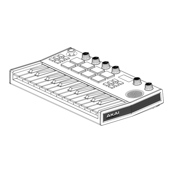
AD21 MIDI 測試作業指導手冊 Unit Cosmetic 機種外觀 Software Installation 測試軟體安裝 Testapp Instruction 測試軟體操作方法 Revision Issue Date Comments V1.4 2021/7/27 Modify Pad Test describe(color) V1.3 2021/7/26 Modify Pad Test describe Update version for MP V1.2 2021/7/20 Modify audio test V1.1... - Page 16 Unit Cosmetic 機種外觀...
- Page 17 Software Installation 測試軟體安裝 Please install AD21Test_20210505.exe...
- Page 18 Testapp Instruction 測試軟體操作方法 Note: During testing, icon means not tested. Yellow Green icon means in testing. Blue icon means test pass. 測試過程中,紅色的圖控元件表示尚未進行測驗;黃、綠色的圖控元件表示測驗中;藍色的圖 控元件表示測驗正確。 Running Test App 1. Open test app 打開測試軟件 2. Plug USB cable to PC. Press and hold [ARP ON] + [FULL LEVEL]. Switch BATT to USB and confirm the unit from OFF to ON, then the unit’s version can be seen on OLED.
- Page 19 Check if the test app connect status is light up in green and check the firmware version via test app and unit display (the firmware version will be appearing on display once connected USB cable to PC under test mode). The firmware version should be v0.21 確認...
- Page 20 綠色代表鍵盤持續按著 Blue color indicates a key passes test. 藍色代表測試通過 Press each key. Verify if they all turn blue. 測試每一個鍵盤確認每一個鍵盤都顯示藍色並通過測試 Move on to next step. 完成測試後進入下一項測試 7. VR Knob Test 旋鈕測試 Red color indicates untested knobs. 紅色代表尚未測試 Green color indicates a knob is turned counterclockwise. 綠色代表旋鈕以逆時針方向旋轉...
- Page 21 9. Encoder Test Turn Encoder clockwise shows Green color. 轉動 Encoder,先正轉一圈軟體會顯示綠色 Then turn Encoder counterclockwise shows Blue color indicates passing test. 再逆轉一圈顯示藍色表示測試 Pass If turn Encoder counterclockwise first, yellow color is shown. 若先逆轉一圈則會顯示黃色 Then turn clockwise shown Blue color indicates passing test 再正轉一圈亦會顯示藍色表示測試...
- Page 22 儲存後 OLED 會顯示 Joystick Setting OK! 14. Test complete 測試完成 When all tests are done, the testapp application will show complete. 完成以上測試,測試畫面下面即會出現 Complete...
- Page 23 2N4403 DGND DGND MUTE 47KΩ 10uF/16V 4.7K MBT4401 47uF/6.3V DGND DGND AOUTR 0Ω 10uF/16V Title: DGND DGND AD21 MAIN PCB 100K 100pF +4.2V DGND Size Number Revision BAV99 PC20A008 DGND DGND Date : 2021/6/28 Sheet File Name: Design By :...
- Page 24 NOTE REPEAT KBD_ROW6 SW12 SW13 KBD_COL0 KBD_ROW0 KBD_ROW0 KBD_ROW7 KNOB BANK A/B FULL LEVEL KEY_COL0 KEY_COL1 Title: Key SCAN AD21 MAIN PCB Size Number Revision PC20A008 Date : 2021/6/28 Sheet TO KEYBOARD DGND File Name: Design By : Approval Check...
- Page 25 S_D+3.3V C100 0.1uF S_A+3.3V C101 10uF/16V C103 S_DGND 0.1uF C102 4.7uF C105 S_AOUTL 0.1uF C104 S_AOUTR 0.1uF S_D+3.3V C106 0.1uF S_D+3.3V R115 R114 S_DGND S_SAM2635_RX S_SAM2635_TX S_SAM2635_RX MIDI IN S_STIN FOR PROGRAM ONLY(NC) S_SAM2635_TX MIDI OUT S_STOUT S_SAM2635_RST S_D+3.3V S_D+3.3V R116 CDPG-XIO S_DGND...
Need help?
Do you have a question about the AD21 and is the answer not in the manual?
Questions and answers