Advertisement
Quick Links
Product Manual
iMech Series
Microprocessor-Based Engine Management System
For Mechanical Engines
Part Number: C3M-100-AS
Revision: 1.2
______________________________________________________________________________________________________________________________________
Copyright Controls, Inc.
P.O. Box 368 • Sharon Center, OH 44274
Phone 330.239.4345 • Fax 330.239.2845 • www.controlsinc.com
Advertisement

Related Manuals for Controls iMech Series


Summary of Contents for Controls iMech Series
- Page 1 Product Manual iMech Series Microprocessor-Based Engine Management System For Mechanical Engines Part Number: C3M-100-AS Revision: 1.2 ______________________________________________________________________________________________________________________________________ Copyright Controls, Inc. P.O. Box 368 • Sharon Center, OH 44274 Phone 330.239.4345 • Fax 330.239.2845 • www.controlsinc.com...
- Page 2 1.1 The C3M-100-AS is a sealed microprocessor-based engine control system for industrial engines. It is based on the Controls, Inc. iMech series controller platform with a Freescale 8 bit processor. 1.2 The product is packaged into a water tight, polycarbonate enclosure for maximum durability. The controller is plug &...
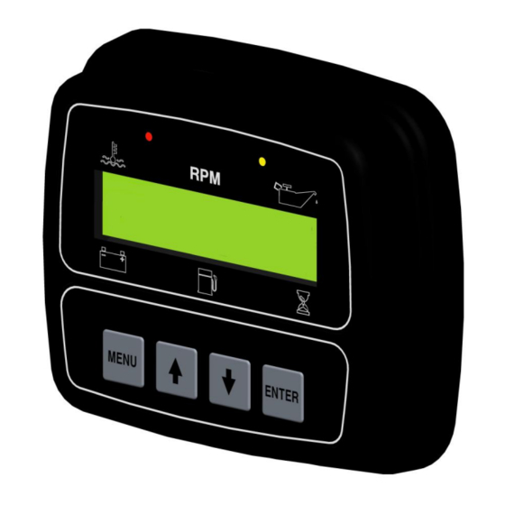
- Page 3 CONTROLS, INCORPORATED C O N T R O L S Y S T E M S & S O L U T I O N S 2) Interface 2.1 Display – The backlit digital display is 1”H x 4”W with two rows of 16 characters. Character height is approximately ½”.
- Page 4 CONTROLS, INCORPORATED C O N T R O L S Y S T E M S & S O L U T I O N S 3) Enclosure 3.1 Sealed Polycarbonate Enclosure 3.2 O-Ring Seal 3.3 Four 10-32 Brass bosses used to mount unit to sheet metal or vibration isolators.
-
Page 5: Panel Operation
CONTROLS, INCORPORATED C O N T R O L S Y S T E M S & S O L U T I O N S 4) Panel Operation 4.1.1 Power Up – Unit performs a power up self-test. Initialization screen displays firmware version. LEDs are illuminated for operation verification. - Page 6 CONTROLS, INCORPORATED C O N T R O L S Y S T E M S & S O L U T I O N S 4.1.3 Acquiring Information – Panel begins monitoring sensor inputs. Values are displayed. If no information is available due to a sensor not being connected, the display shows dashed lines.
- Page 7 CONTROLS, INCORPORATED C O N T R O L S Y S T E M S & S O L U T I O N S Engine Warning – When the iMech detects a parameter is outside of its normal operating range, the 4.1.5...
- Page 8 CONTROLS, INCORPORATED C O N T R O L S Y S T E M S & S O L U T I O N S Alarm Logging – Anytime a warning or shutdown condition occurs, the panel will store the event in 4.1.7...
- Page 9 CONTROLS, INCORPORATED C O N T R O L S Y S T E M S & S O L U T I O N S Throttle Operation – When using the iMech to control engine speed, a third party governor or other 4.1.9...
-
Page 10: External Connectors
CONTROLS, INCORPORATED C O N T R O L S Y S T E M S & S O L U T I O N S 5) External Connectors 5.1 C3M-100 Module Connector - The C3M-100 module is connected to the internal wiring harness via a 14-pin TYCO plug. -
Page 11: Controller Menus
CONTROLS, INCORPORATED C O N T R O L S Y S T E M S & S O L U T I O N S 6) Controller Menus 6.1 The control panel has menus to view engine and controller parameters. These menus are accessible via the four-button pad located on the face of the control panel. - Page 12 CONTROLS, INCORPORATED C O N T R O L S Y S T E M S & S O L U T I O N S 6.3.2 Navigation 1. Press MENU to select the next menu category. 2. Press UP to view or edit the specific screen(s) in the category.
- Page 13 CONTROLS, INCORPORATED C O N T R O L S Y S T E M S & S O L U T I O N S 6.3.3 Password Entry The password screen is provided to restrict the edit of sensitive values to authorized personnel.
- Page 14 CONTROLS, INCORPORATED C O N T R O L S Y S T E M S & S O L U T I O N S 6.3.5 Exiting 1. Press and hold the MENU key & simultaneously press the ENTER key.
-
Page 15: Module Configuration
CONTROLS, INCORPORATED C O N T R O L S Y S T E M S & S O L U T I O N S 7) Module Configuration Allows the user or OEM to set up the proper behavior and functionality of the module. Options include the following. - Page 16 CONTROLS, INCORPORATED C O N T R O L S Y S T E M S & S O L U T I O N S 8) Sender Configuration Allows the user or OEM to set up the proper sender types and engine safety limits of the module. Options include the following.
- Page 17 S O L U T I O N S 10) Warranty CONTROLS, INC. is herein called “Seller”. The person, firm or corporation to whom or which the sale is made is herein called “Buyer”. Seller warrants to the Buyer that all products furnished under this order will conform to Seller’s specification, drawings as...
Need help?
Do you have a question about the iMech Series and is the answer not in the manual?
Questions and answers