
Related Manuals for Controls WIZARD 2 50-C92AXX


Summary of Contents for Controls WIZARD 2 50-C92AXX
- Page 1 50-C92AXX, 50-C13A0X 50-C23A0X, 50-C34A0X Compression and flexural testers MANUALE DI ISTRUZIONI INSTRUCTION MANUAL...
-
Page 3: Table Of Contents
Compression platens ......................27 Hydraulic power unit ......................27 WIZARD 2 display unit..................... 27 Connections ........................28 Identification plate ......................29 Commands and controls ....................30 2.7.1 Flow control valve ......................31 Technical specifications ..................... 32 3. INSTALLATION Shipment ..........................39 Unpacking and inspection .................... - Page 4 Manuale di Istruzione Instruction Manual 4.2.3.2 UNIT OF MEASURE option ..................67 4.2.3.3 DELETE ARCHIVE option ................... 67 4.2.3.4 RESULTS option ......................68 4.2.3.5 LANGUAGE option ...................... 68 4.2.4 CALIBRATION menu ....................69 Carry out a test ........................70 4.3.1 Selection of the frame to use for 50-C92A2X machine..........
- Page 5 This instruction manual is an integral part of the machine and should be read before using the machine and be safely kept for future reference. CONTROLS reserves all rights of this manual, no part or whole can be copied without the written permission of CONTROLS.
-
Page 6: Introduction
Manuale di Istruzione Instruction Manual INTRODUCTION NOTE: The present manual is updated for the product it is sold with in order to grant an adequate reference in operating and maintaining the equipment. The manual may not reflect changes to the product not impacting service operations. 50-C92AXX These Multipurpose compression / flexure testers have been designed for various applications in which a limited maximum load is requested, together with a large testing... - Page 7 Manuale di Istruzioni Instruction Manual The automatic test procedure, once the specimen has been positioned and centered and the machine switched on is: • Set test parameters, including load rate, on the touch screen (can be avoided by default for repetitive tests); •...
- Page 8 Manuale di Istruzione Instruction Manual Here is the list of models available and their relevant main specifications: Single testing chamber models 50-C92A02 600 kN cap., WIZARD 2 Semi-automatic COMPACT-Line compression tester, load measurement with pressure transducer. 230 V, 50-60 Hz, 1ph 50-C92A03 Same as above but 220V, 60 Hz, 1ph 50-C92A04...
- Page 9 Manuale di Istruzioni Instruction Manual 50-C13A0X/C23A0X/C34A0X Frame Rigid welded steel construction. Spherical seat allows free alignment at the initial contact with the specimen. Compression platens See table. Traceable certificate of surface hardness available on request. Wizard, Semi-Automatic power and control system Dual stage pump: low pressure/high delivery for fast piston approach and high pressure/low volume for loading.
- Page 10 Manuale di Istruzione Instruction Manual Here is the list of models available and their relevant main specifications: 50-C13A02 WIZARD 2, Semi- Automatic Compact-Line Gen. Util. compression tester, 1500 kN cap., for cubes up to 150 mm and cylinders up to dia. 160 x 320 mm. 230 V, 50 Hz, 1 ph. 50-C13A03 Same as above but 220 V, 60 Hz, 1 ph.
-
Page 11: Icons Appearing In The Manual
Manuale di Istruzioni Instruction Manual Icons appearing in the manual This icon indicates a NOTE; please read thoroughly the items marked by this picture. This icon indicates a WARNING message; the items marked by this icon refer to the safety aspects of the operator and/or of the service engineer. Rev.1 EN 23/08/2018... -
Page 12: Manual Revision History
Manuale di Istruzione Instruction Manual Manual revision history Revision/Date Change description Rev. 1 Manual release August 23 2018 23/08/2018 Rev.1 EN... -
Page 13: Symbols Used
Manuale di Istruzioni Instruction Manual Symbols used In this manual and on the equipment itself, apart from the symbols indicated on the control panel, the following icons are also used: Symbol Description Mains switch: O = device not connected to the mains line I = device connected to the mains line Emergency stop switch Dangerous voltage... -
Page 14: Intended Use And Improper Use
Never use the machine for reasons other than those for which it was designed and manufactured. Any other use of the machine is to be considered improper, not foreseen and hence dangerous. CONTROLS will not be responsible for improper use of the machine. 23/08/2018 Rev.1 EN... -
Page 15: Safety Information
Safety information WARNING: Please read this chapter thoroughly. CONTROLS designs and builds its devices complying with the related safety requirements; furthermore it supplies all information necessary for correct use and the warnings related to use of the equipment. CONTROLS will not to be held responsible for: •... - Page 16 Manuale di Istruzione Instruction Manual The machine is equipped with the following devices to limit the residual risks in using it: • Emergency button that switches OFF the unit once pressed, thus stopping the raising of the piston; • Max. pressure valve to avoid machine overloading; Emergency button Max.
- Page 17 Manuale di Istruzioni Instruction Manual • Ram travel switch to prevent the excessive piston travel; when triggered it disables the functioning of the pump motor; Limit switch Fig. 1-3 • Front door and rear transparent fragment guard; Front fragment guard Fig.
- Page 18 Manuale di Istruzione Instruction Manual • On the motor connection box, input for ram travel microswitches to prevent the excessive piston travel; when triggered it disables the functioning of the pump motor; Connector for overtravel microswitch Fig. 1-5 • Access panels to internal parts locked with screws. 23/08/2018 Rev.1 EN...
- Page 19 Manuale di Istruzioni Instruction Manual The following table lists those parts of the equipment that may present some residual risks for the safety of the personnel if the instructions provided in this manual are not duly followed. Personnel Area with residual risks Operator The sample during load-unloading phase from the frame, due to its weight and sharp surfaces.
- Page 20 Do not use the USB port to re-charge batteries of external devices (e.g mobile phone, audio-video players, etc.). It is also mandatory to connect/disconnect the USB memory stick with the unit OFF. CONTROLS will not be held responsible for damages to persons and/or properties in case these instructions are not strictly followed. WARNING: When operating with the covers open/removed and the unit is attached to the mains line, care must be taken as high voltage is present in some parts of the unit (e.g.
- Page 21 Make sure to use proper fixing bolts according to the type of floor of the installation place. CONTROLS cannot be considered responsible in case of injures to the operator or damages to the equipment if the above instructions are not duly followed.
- Page 22 WARNING: Failing to perform the recommended maintenance actions or maintenance performed by unauthorized people can void the warranty. CONTROLS will not be responsible for maintenance and service actions performed by unauthorized people. WARNING: Before opening/removing the covers, disconnect the mains supply to the device and wait at least 5 minutes.
- Page 23 Refer to qualified service organization authorized by CONTROLS to carry out the maintenance actions described in the chapter “Authorized service engineer maintenance action”. CONTROLS has not to be held responsible for damages to the equipment and/or injuries to personnel in case the above is not strictly followed.
-
Page 24: Environmental Risks And Disposal
Manuale di Istruzione Instruction Manual Environmental risks and disposal INFORMATION TO THE OWNER OF THE EQUIPMENT The above symbol, when attached to the equipment or to the relevant packaging, indicates that the product must be disposed of separately from other rubbish at the end of its useful life. -
Page 25: Ce Declaration
Manuale di Istruzioni Instruction Manual CE declaration This page shows a copy of the CE declaration. The original is supplied with the equipment as a separate document. Rev.1 EN 23/08/2018... -
Page 26: Description
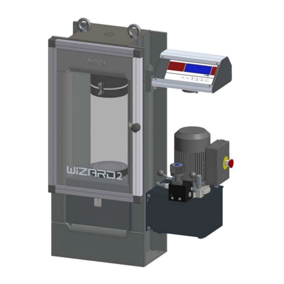
Manuale di Istruzione Instruction Manual DESCRIPTION Refer to the following figures for main components identification. Fig. 2-1 Machine with 600 kN frame, code 50-C92A0X Ref. Description Upper platen with spherical seat Front guard Lower platen Piston travel indicator Control unit Flow control valve AC motor dual stage hydraulic pump with MOTOR ON switch EMERGENCY BUTTON... - Page 27 Manuale di Istruzioni Instruction Manual Fig. 2-2 Machine with 500 kN frame, code 50-C92A1X Ref. Description Load cell Upper platen with spherical seat Front guard Lower platen Piston travel indicator Control unit Flow control valve AC motor dual stage hydraulic pump with MOTOR ON switch EMERGENCY BUTTON ON/OFF Hydraulic valve Speed selector (rapid approach, test speed)
- Page 28 Manuale di Istruzione Instruction Manual Fig. 2-3 – Machine with 2 frames (600 kN and 15 kN), code 50-C92A2X Ref. Description Load cell on 15 kN frame Upper platens with spherical seats Front guard Lower platen Piston travel indicator Control unit Flow control valve AC motor dual stage hydraulic pump with MOTOR ON switch EMERGENCY BUTTON...
-
Page 29: Frames
Manuale di Istruzioni Instruction Manual Frames High rigidity solid one piece steel frame. Spherical seat allows free alignment at the initial contact with the specimen. There is a 600 kN frame, model code 50-C92A0X and a 500 kN frame, model code 50-C92A1X. There is also a second testing chamber with a 15 kN frame, only in model code 50- C92A2X. -
Page 30: Connections
Do not use the USB port to re-charge batteries of external devices (e.g mobile phone, audio-video players, etc.). It is also mandatory to connect/disconnect the USB memory stick with the unit OFF. CONTROLS will not be held responsible for damages to persons and/or properties in case these instructions are not strictly followed. 23/08/2018... -
Page 31: Identification Plate
Manuale di Istruzioni Instruction Manual Identification plate The identification plate is located on the rear side of the equipment control unit, near the power cable. Fig. 2-5 Rev.1 EN 23/08/2018... -
Page 32: Commands And Controls
Manuale di Istruzione Instruction Manual Commands and controls This chapter describes the commands and controls of the equipment. The operator’s interface description and the use of the buttons of the control unit is provided in chapter 4.2 of the present manual. -
Page 33: Flow Control Valve
Manuale di Istruzioni Instruction Manual 2.7.1 Flow control valve Fig. 2-7 Ref. Description Load gradient adjustment knob (clockwise to decrease; counter clockwise to increase) Flow control lever (back for rapid approach; forward to control load rate with the load gradient adjustment knob) Oil supply lever (up to recycle oil in the tank;... -
Page 34: Technical Specifications
Manuale di Istruzione Instruction Manual Technical specifications Main characteristics 50-C92AXX WIZARD 2 Compression and Flexural machines, multipurpose Product models CONTROLS Liscate (MI) Italy Manufacturer Type Single Chamber Single Chamber Double Chamber Models 50- C92A0X C92A1X C92A2X Product code 230VAC version 50-60... - Page 35 Manuale di Istruzioni Instruction Manual Main characteristics Model 50- C13A02 C23A02 C34A02 C13A04 C23A04 C34A04 Capacity kN (lbf) 1500 (335,000) 2000 (450,000) 3000 (660,000) Max vertical daylight, 340 (13.4") 350 (13.8") 350 (13.8") mm* (inches) Horizontal daylight, mm 265 (10.4") 340 (13.4") 370 (14.6") (inches)
- Page 36 Make sure to use proper fixing bolts according to the type of floor of the installation place. CONTROLS cannot be considered responsible in case of injures to the operator or damages to the equipment if the above instructions are not duly followed.
- Page 37 Manuale di Istruzioni Instruction Manual Fig. 2-9 Dimension and fixing of 50-C92A1X Rev.1 EN 23/08/2018...
- Page 38 Manuale di Istruzione Instruction Manual Fig. 2-10 Dimension and fixing of 50-C92A2X 23/08/2018 Rev.1 EN...
- Page 39 Manuale di Istruzioni Instruction Manual It is possible to mount a pedestal (accessory code: 50-C99/B) on all 3 types of machines: 50-C92A0X 50-C92A1X 50-C92A2X Fig. 2-11 Rev.1 EN 23/08/2018...
-
Page 40: Installation
The information in this chapter is intended for authorized service-trained personnel. CONTROLS can supply the assistance and the necessary technical advice for pre- installation, all the pre-installation phases are at the purchaser’s charge and must be performed complying with the indications given below. -
Page 41: Shipment
Manuale di Istruzioni Instruction Manual Shipment The equipment is normally shipped in a wooden crate having the following dimensions and gross weight depending on the model: Minimum Overall dimensions Models Gross weight fork lift (L x D x H) length 50-C92A0X with 386 Kg... - Page 42 Manuale di Istruzione Instruction Manual Fig. 3-2 60 Kg wooden crate Fig. 3-3 70 Kg wooden crate 23/08/2018 Rev.1 EN...
- Page 43 Manuale di Istruzioni Instruction Manual WARNING: Raising and moving of the equipment must be performed by people properly trained and equipped with suitable personal protection devices (e.g. gloves, helmet, etc.). Failure to follow the instructions above may endanger the personnel involved. WARNING: The wooden crate is high;...
-
Page 44: Unpacking And Inspection
CONTROLS representative. If the shipping container is damaged or shows sign of stress, notify the carrier as well as the CONTROLS representative. Save the shipping material for carrier’s inspection. Also take some pictures. Here follows the procedure for the unpacking of the equipment. -
Page 45: How To Remove The Equipment From The Shipping Crate
Manuale di Istruzioni Instruction Manual 3.2.1 How to remove the equipment from the shipping crate The following table shows the net weight of the different models of the equipment: Model Net weight 50-C92A0X 270 Kg approx. 50-C92A1X 280 Kg approx. 50-C92A2X 340 Kg approx. - Page 46 Manuale di Istruzione Instruction Manual WARNING: If the instructions to remove the equipment from the shipping box are not carefully followed, damages to the equipment cabinet may result. This will void the warranty terms of the equipment. WARNING: Raising and moving of the equipment must be performed by people properly trained and equipped with suitable personal protection devices (e.g.
-
Page 47: Positioning Of The Unit And Space Requirements
Manuale di Istruzioni Instruction Manual Positioning of the unit and space requirements WARNING: Considering the weight of the equipment and the footprint (see chapter 2.8), check the maximum allowed floor load before installation. The unit must be placed on a flat and level surface. The area around the equipment must be kept free from obstacles and from substances that may cause sliding of the personnel. - Page 48 Make sure to use proper fixing bolts according to the type of floor of the installation place. CONTROLS cannot be considered responsible in case of injures to the operator or damages to the equipment if the above instructions are not duly followed.
-
Page 49: Mounting The Control Unit
Manuale di Istruzioni Instruction Manual Mounting the control unit The control unit assembly is normally shipped dismantled from the frame. To mount it on the frame: 1. Fit the control unit assembly shaft into the relevant housing on the right-hand side of the frame;... -
Page 50: Positioning Of The Display
Manuale di Istruzione Instruction Manual Positioning of the display Depending on the lighting of the laboratory and the height of the operator, it may be necessary to adjust the positioning of the display to ensure optimum visibility. 1. Loosen the screw shown in next pictures; Screw to loosen Fig. -
Page 51: Electrical Requirements
Manuale di Istruzioni Instruction Manual Electrical requirements The next table shows the electrical specifications of the equipment: Item Specifications Mono phase voltage 110VAC/220VAC/230VAC +10%, -10% Frequency 50-60Hz/60Hz Maximum power 750W The equipment shall be connected to a proper earth system, the efficiency of which shall be checked by qualified personnel. -
Page 52: Electrical Connections
Manuale di Istruzione Instruction Manual Electrical connections The sockets for electrical connection are on the rear panel of the equipment, these are for the load sensors, displacement transducers, USB memory stick and LAN ports, and mains supply fitted with filter, fuses and mains switch. 1. - Page 53 Manuale di Istruzioni Instruction Manual 3. Also connect the overtravel microswitch of the frame to the relevant socket on the rear of the motor box; Connector for overtravel microswitch Fig. 3-11 4. In case two frames are connected to the same hydraulic unit, a y-cable must be used (e.g.
-
Page 54: Hydraulic Connections
Manuale di Istruzione Instruction Manual Hydraulic connections This chapter explains where to connect the hydraulic hose to supply the frame. In case the device is equipped with the dual output hydraulic block (code C10B/2F to be installed in the factory) it will be possible to connect a second frame. WARNING: To avoid direct contact with the oil of the hydraulic circuit, always wear protective gloves while performing the checking. - Page 55 Due to the high pressure inside the hydraulic circuit (up to 650 bars) only tubes approved by CONTROLS can be used. CONTROLS will not be responsible for damages to the equipment or personnel injures in case of use of improper material and/or operations not carried out by authorized technical personnel.
- Page 56 Manuale di Istruzione Instruction Manual 3. If the capacity of the second frame is higher than the one of the frame already connected to the equipment, the max. pressure valve might need to be re-adjusted: a. Locate the max. pressure adjustment valve; b.
-
Page 57: Installation Of The Printer Paper
Manuale di Istruzioni Instruction Manual Installation of the printer paper The printer (optional) is supplied with a roll of thermal paper which should be installed before starting the unit. Proceed as follows: 1. Open the paper roll compartment by pressing the OPEN key; 2. -
Page 58: Use Of The Equipment
Manuale di Istruzione Instruction Manual USE OF THE EQUIPMENT This chapter describes the operator’s interface and the execution of a test. WARNING: All safety devices must be functional at all times. Damaged protective covers or devices must be replaced immediately. When safety components are replaced, the protective devices are to be properly attached and tested. -
Page 59: Switching On The Equipment
It is also mandatory to connect/disconnect the USB memory stick with the unit OFF. CONTROLS will not be held responsible for damages to persons and/or properties in case these instructions are not strictly followed. The green light of the printer (optional) will lit, the display will first show a start up screen and after 5 seconds a screen with the status of the system interfaces;... -
Page 60: Main Menu
Manuale di Istruzione Instruction Manual MAIN MENU The MAIN MENU is accessed after turning ON the and pressing the key twice. Fig. 4-4 It comprises the following choices: • TEST RUN: this is the screen used to conduct tests on specimens; it allows inputting the specimen data, units, load rate and peak sensitivity;... -
Page 61: Test Run Menu
Manuale di Istruzioni Instruction Manual 4.2.1 TEST RUN menu After accessing TEST RUN menu, if two channels have been activated into the system (see chapter 6.1.1 for channel activation), use the keys to select the desired channel and press the key to confirm it. - Page 62 Manuale di Istruzione Instruction Manual • RATE and UNIT: reference load rate for the test. It will be used by the system during the execution of the test to provide indications to the operator for proper setting of the load control valve of the compression machine. Use the keys to scroll the different digits and the keys to set the figure;...
- Page 63 Manuale di Istruzioni Instruction Manual Fig. 4-8 This screen shows: A. The channel number selected for the test B. The actual load value measured by the load sensor connected to the WIZARD 2 C. The strength (resistance) of the sample D.
- Page 64 Manuale di Istruzione Instruction Manual Next instructions describe its use in the different phases of the test. 2) Load control phase: 1) Beginning of the test (rapid approach): Lever A up and lever B slowly forward: Piston Lever A up and Lever B back: Maximum piston speed upwards controlled by load rate control speed upwards;...
- Page 65 Manuale di Istruzioni Instruction Manual Start the hydraulic pump of the compression machine and apply load; Before the sample comes in touch with the machine upper platen, zero the load reading on the WIZARD 2 display by pressing the key; The system will start updating the load value on the screen once the PRELOAD value is reached (see chapter 6.1.1 to set the PRELOAD value);...
- Page 66 It is also mandatory to connect/disconnect the USB memory stick with the unit OFF. CONTROLS will not be held responsible for damages to persons and/or properties in case these instructions are not strictly followed. To proceed with a further test, press the key;...
-
Page 67: Archive Menu
Manuale di Istruzioni Instruction Manual 4.2.2 ARCHIVE menu Saved files are stored in an USB memory stick to be connected on the dedicated port located on the rear panel of the WIZARD 2. The number of tests that can be stored depends on the capacity of the memory stick. -
Page 68: Options Menu
Manuale di Istruzione Instruction Manual 4.2.3 OPTIONS menu Accessing the OPTIONS from the MAIN MENU, the system will show the following screen. Fig. 4-13 Use the to select the desired option and the key to proceed. 4.2.3.1 CLOCK option Select the CLOCK option to set DATE AND TIME. Fig. -
Page 69: Unit Of Measure Option
Manuale di Istruzioni Instruction Manual 4.2.3.2 UNIT OF MEASURE option It allows selecting among three different units: • kN and mm • Ton and mm • Lbf and inch. Fig. 4-15 Once entered, use the keys to select the desired unit, then key twice to confirm the change and return to the OPTIONS menu. -
Page 70: Results Option
Manuale di Istruzione Instruction Manual 4.2.3.4 RESULTS option Access this screen to set the following TEST RESULT OPTIONS: • AUTOPRINT: in case it is ENABLED, the system will automatically print the data at the end of the test, on the internal printer (optional device). In case it is DISABLED, the printout can take place by pressing the key at the end of the test;... -
Page 71: Calibration Menu
WARNING: The CALIBRATION menu is reserved to the authorised service personnel. CONTROLS will not be responsible for any damage caused by improper setting of these parameters. Warranty will be void if this menu is used by unauthorised personnel. -
Page 72: Carry Out A Test
(e.g. if the value is too high the machine will not be able to sense the failure of the sample and therefore will continue pressing the sample and never stop). This may result in damages to the equipment and/or danger for the operator. CONTROLS will not be considered responsible in these events. - Page 73 Manuale di Istruzioni Instruction Manual Before starting any test check that: • The test frame is free from residual of previous sample and that the surfaces of the platens are clean; • Depending on the size of the sample, use proper distance pieces to reduce the daylight on the press (leave a gap of at least 3-4mm), also considering that the piston total travel is 50mm.
-
Page 74: Selection Of The Frame To Use For 50-C92A2X Machine
Manuale di Istruzione Instruction Manual 4.3.1 Selection of the frame to use for 50-C92A2X machine Depending on the type of test to perform, select the relevant frame by means of the frame selector lever here after shown: • Lever UP to select Frame #1; •... -
Page 75: Use Of The Load Control Valve
Manuale di Istruzioni Instruction Manual 4.3.2 Use of the load control valve The load rate is controlled using the special valve with dial gauge handle mounted on the pump. The correct load rate can be set by following the load rate indicator on the WIZARD 2 and rotating the load rate valve either clockwise or counter clockwise. -
Page 76: Testing A Sample
Manuale di Istruzione Instruction Manual 4.3.3 Testing a sample Switch ON the machine and wait 15 minutes warm up time; Place the sample in the test frame and close front door and rear guards (see previous WARNIGS); After accessing TEST RUN menu, if two channels have been activated into the system (see chapter 6.1.1 for channel activation), use the keys to select the desired channel and press the... - Page 77 Manuale di Istruzioni Instruction Manual Press the key to save (or the button to keep the old parameters) and to access to the TEST EXECUTION screen; Fig. 4-24 When ready, turn ON the pump motor by pressing the relevant switch (note that the pump motor switch is self retaining when the mains electricity supply is connected);...
- Page 78 Manuale di Istruzione Instruction Manual 8. Once the sample comes into contact with the upper platen/bearer, with lever A up, turn lever B slowly forward to control the speed of the piston with the flow control valve; Fig. 4-26 The system will start updating the load value on the screen once the PRELOAD value is reached (see chapter 6.1.1 to set the PRELOAD value);...
- Page 79 Manuale di Istruzioni Instruction Manual Fig. 4-28 11. When the sample fails, the display will show the test results (maximum load and resistance) and the system will emit an audible alarm (5 beeps) to inform the operator; the trend indicator will also show the symbol *****. In case the full scale of the system was reached before the failure of the sample, the system will only emit the audible alarm;...
- Page 80 It is also mandatory to connect/disconnect the USB memory stick with the unit OFF. CONTROLS will not be held responsible for damages to persons and/or properties in case these instructions are not strictly followed. 14. To proceed with a further test, press the key;...
-
Page 81: Stopping The Cycle Via The Emergency Button
Manuale di Istruzioni Instruction Manual Stopping the cycle via the Emergency button In case dangerous conditions are encountered during the execution of a test cycle, it is possible to stop the machine by pressing the EMERGENCY BUTTON. EMERGENCY BUTTON Fig. 4-31 Rev.1 EN 23/08/2018... - Page 82 Manuale di Istruzione Instruction Manual Pressing this button will stop the pump motor (its switch will be released and will return in the “0” position) thus stopping the movement of the piston. To release the hydraulic pressure, turn lever B slowly back and lever A down. Fig.
-
Page 83: Switching Off The Unit
Manuale di Istruzioni Instruction Manual Switching off the unit At the end of a test, make sure data storing into the USB memory have been completed, then remove residuals of the samples. Return the unit to the MAIN MENU and switch the equipment OFF via the mains switch on the control unit. -
Page 84: Maintenance
WARNING: Failing to perform the recommended maintenance actions or maintenance performed by unauthorized people can void the warranty. CONTROLS will not be responsible for maintenance and service actions performed by unauthorized people. WARNING: Before opening/removing the covers, disconnect the mains supply to the device and wait at least 5 minutes. - Page 85 Due to the high pressure inside the hydraulic circuit (up to 650 bars) only tubes approved by CONTROLS can be used. CONTROLS will not be responsible for damages to the equipment or personnel injures in case of use of improper material and/or operations not carried out by authorized technical personnel.
-
Page 86: Operator's Preventive Maintenance
Manuale di Istruzione Instruction Manual Operator’s preventive maintenance The inspections made directly by the operator are the following: Action When Check to ensure that there is no Operator Before every working session external damage to the equipment, which could jeopardise the safety of Clean and dry platens, distance Operator At the end of each working... -
Page 87: Checking The Status Of The Safety Devices
Manuale di Istruzioni Instruction Manual 5.1.1 Checking the status of the safety devices • Emergency button that switches OFF the unit once pressed, thus stopping the raising of the piston; • Max. pressure valve to avoid machine overloading; Emergency button Fig. - Page 88 Manuale di Istruzione Instruction Manual • Ram travel switch to prevent the excessive piston travel; when triggered it disables the functioning of the pump motor; Limit switch Fig. 5-2 • Front door and rear transparent fragment guard; Front fragment guard Fig.
- Page 89 Manuale di Istruzioni Instruction Manual • On the motor connection box, input for ram travel microswitches to prevent the excessive piston travel; when triggered it disables the functioning of the pump motor. Connector for overtravel microswitch Fig. 5-4 Rev.1 EN 23/08/2018...
-
Page 90: Checking The Oil Level In The Tank
Manuale di Istruzione Instruction Manual 5.1.2 Checking the oil level in the tank WARNING: To avoid direct contact with the oil of the hydraulic circuit, always wear protective gloves while performing the checking. Check the oil level in the tank via the transparent level indicator (the oil should be max. -
Page 91: Authorized Service Engineer Maintenance Actions
Refer to qualified service organization authorized by CONTROLS to carry out the maintenance actions described in the chapter “Authorized service engineer maintenance action”. CONTROLS has not to be held responsible for damages to the equipment and/or injuries to personnel in case the above is not strictly followed. -
Page 92: Checking The Centering Of The Ram Assembly
Manuale di Istruzione Instruction Manual 5.2.1 Checking the centering of the ram assembly The proper centering of the ram assembly assures proper and uniform distribution of the force to the sample during the execution of the compression test. This check is normally carried out before checking the calibration of the system and checking the stability of the frame through the force transfer test with the strain gauged column. - Page 93 Manuale di Istruzioni Instruction Manual 4. If it is not centered more than 1mm in one or more directions, loosen the ram fixing nuts and screws and use a rubber hammer to re-center it properly; Fig. 5-8 5. Also check that the ram is properly positioned from a rotational point of view by taking as reference the position of the oil supply tube with respect to the columns of the frame on the rear of the ram;...
-
Page 94: Checking The Hydraulic Circuit
Due to the high pressure inside the hydraulic circuit (up to 650 bars) only tubes approved by CONTROLS can be used. CONTROLS will not be responsible for damages to the equipment or personnel injures in case of use of improper material and/or operations not carried out by authorized technical personnel. - Page 95 Manuale di Istruzioni Instruction Manual Fig. 5-11 In case of oil leakages, check the single item(s) and replace the relevant gasket/O- ring; Then check the oil level in the tank (refer to chapter 5.1.2) and, if needed, re-fill the oil tank as described in chapter 5.2.6; At the end, use compressed air to clean the slot between piston and cylinder and the base of the compression frame.
-
Page 96: Checking The Status Of Distance Pieces
Manuale di Istruzione Instruction Manual 5.2.3 Checking the status of distance pieces To assure proper and uniform distribution of the force to the sample during the execution of the compression test, status of distance pieces and platens must be periodically checked. -
Page 97: Performing The Maintenance Of The Spherical Seat
Refer to qualified service organization authorized by CONTROLS to carry out the maintenance actions described in the chapter “Authorized service engineer maintenance action”. CONTROLS has not to be held responsible for damages to the equipment and/or injuries to personnel in case the above is not strictly followed. -
Page 98: Checking The Calibration Of The Channels
WARNING: The CALIBRATION menu is reserved to the authorised service personnel and should only be entered when the calibration needs to be changed. CONTROLS will not be responsible for any damage caused by improper setting of these parameters. Warranty will be void if this menu is used by unauthorised personnel. - Page 99 Manuale di Istruzioni Instruction Manual After selecting the CALIBRATION, if two channels have been activated into the system (see chapter 6.1.1 for channel activation), use the keys to select the desired channel and press the key to confirm it. Fig. 5-13 Otherwise the system will directly go to the following screen.
-
Page 100: Calibration Verification
Manuale di Istruzione Instruction Manual 5.2.5.1 Calibration verification To verify the calibration, the unit should be left switched on for at least 15 minutes to allow the thermal equilibrium of the electronic components. Then proceed as follows: Activate the CALIBRATION MENU by selecting the CALIBRATION option on the MAIN MENU;... - Page 101 Manuale di Istruzioni Instruction Manual During this phase, before the reference cell is subjected to any load, zero the reading by pressing the key; NOTE: Do not zero the load reading once the load cell has been subjected to loading. NOTE: key can be pressed several times to zero the load reading on the display before the frame start the loading phase.
- Page 102 Manuale di Istruzione Instruction Manual Adjust the load rate by acting on the flow control valve knob; Fig. 5-18 Once the load cell is under load, a moderate speed should be used, making adjustments with the flow control valve knob as described above. By taking the load rate close to zero it is possible to stop the load increase and maintain an almost constant pressure.
- Page 103 Manuale di Istruzioni Instruction Manual 10. Check the readings given by the WIZARD 2 system against that of the reference load cell. Normally this is done at values of 10%, 15%, 20%, 40%, 60%, 80% and 100% of the full scale of the loadcell. It is also possible to check the calibration at lower loads if the compression frame has been so calibrated;...
-
Page 104: Calibration
Do not enter into this menu for any other reason. Before entering the CALIBRATION menu, it is vital to carefully read and understand the procedure described hereunder. If any doubts remain, contact CONTROLS service department for further clarification. CONTROLS will accept no responsibility for any inconvenience caused by wrongful calibration. - Page 105 Manuale di Istruzioni Instruction Manual If the system linearity is not acceptable within the field 10% to 100% full scale, we recommend the following values, 10%, 20%, 60%, 100%. Particular operator experience or needs may lead be the use of other values. Proceed as here after described to operate the compression machine and achieve the different load steps;...
- Page 106 Manuale di Istruzione Instruction Manual Adjust the load rate by acting on the flow control valve knob; Fig. 5-23 Once the load cell is under load, a moderate speed should be used, making adjustments with the flow control valve knob as described above. By taking the load rate close to zero it is possible to stop the load increase and maintain an almost constant pressure.
- Page 107 Manuale di Istruzioni Instruction Manual 11. After assessing the bit readings at the different load steps (previous step 2), access the EDIT calibration screen by pressing the key, the system will require entering a password; Fig. 5-25 12. Enter the password 00101 by using the keys to select the digits to change and the keys to set it.
- Page 108 Manuale di Istruzione Instruction Manual 13. Enter the first load step (typically 0) on the left column of the first row on the display (use the keys to select the digits to change and the keys to set the figure), then press the key to access the figure on the right column on the display and enter the corresponding bit reading previously recorded;...
-
Page 109: Replacing The Oil Of The Hydraulic Circuit
Manuale di Istruzioni Instruction Manual 5.2.6 Replacing the oil of the hydraulic circuit WARNING: To avoid direct contact with the oil of the hydraulic circuit, always wear protective gloves while performing the checking. Periodically the oil of the hydraulic circuit must be completely replaced. 1. - Page 110 Manuale di Istruzione Instruction Manual 2. Collect the old oil and dispose it in accordance with the local regulations; 3. Refill the tank (6 litres approx.) with the oil type shown in next table; Brand Type Agip ATF Dexron Apilube ATF Dexron Chevron Chevron automatic transmission fluid Elfmatic G...
-
Page 111: Diagnostics & Troubleshooting
Refer to qualified service organization authorized by CONTROLS to carry out the service maintenance actions described in the chapter “Diagnostic and Troubleshooting”. CONTROLS has not to be held responsible for damages to the equipment and/or injuries to personnel in case the above is not strictly followed. -
Page 112: System (Hidden) Menu
Refer to qualified service organization authorized by CONTROLS to carry out the service maintenance actions described in the chapter “Diagnostic and Troubleshooting”. CONTROLS has not to be held responsible for damages to the equipment and/or injuries to personnel in case the above is not strictly followed. - Page 113 Manuale di Istruzioni Instruction Manual Enter the password 00202 by using the keys to select the digits to change and the keys to set it. Confirm it by pressing the key. The SYSTEM MENU is now displayed; Fig. 6-3 The following options are provided in this menu: •...
-
Page 114: Channels Set-Up Option
Manuale di Istruzione Instruction Manual 6.1.1 CHANNELS SET-UP option It allows setting into the WIZARD 2 control unit the working parameters of the frame connected. Fig. 6-4 The following functions are available within this menu. 6.1.1.1 ACTIVE CHANNEL option It allows activating/de-activating the second channel into the unit. To activate/de-activate the second channel press the key to bring the cursor to the CHn selection and use the... -
Page 115: Full Scale And Preload Settings
Manuale di Istruzioni Instruction Manual 6.1.1.2 FULL SCALE and PRELOAD settings Use the key to bring the cursor to the desired parameter to change, the keys to select the digits to change and the keys to set the value. Then press the key to access the next parameter to change. -
Page 116: Serial Number Option
Manuale di Istruzione Instruction Manual 6.1.2 SERIAL NUMBER option This screen allows entering the unit serial number that it is normally set during the manufacturing of the unit and does not need to be changed unless the MEMORY RESET function has been activated (see chapter 6.1.3). The serial number will be shown on the display at switch ON. -
Page 117: Memory Reset Option
It can be used to completely reset the system in case of system memory corruption. WARNING: Do not use the MEMORY RESET function unless authorized by CONTROLS Service department. CONTROLS will not be held responsible for damages to the equipment and/or injuries to personnel in case the above is not strictly followed. - Page 118 Manuale di Istruzione Instruction Manual Note: 23/08/2018 Rev.1 EN...
- Page 119 Manuale di Istruzioni Instruction Manual Note: Rev.1 EN 23/08/2018...
Need help?
Do you have a question about the WIZARD 2 50-C92AXX and is the answer not in the manual?
Questions and answers
While I calibrate using a national standard calibrated and traceable lodecell my machine reading has a large error out of the tolerance limit. So what could be the possible causes?