Table of Contents
Advertisement
Quick Links
Advertisement
Table of Contents

Related Manuals for Controls 15-D0410


Summary of Contents for Controls 15-D0410
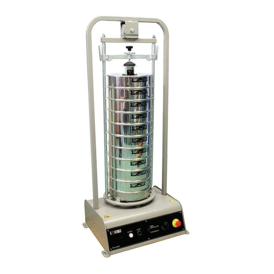
- Page 1 15-D0410 ELECTRO-MECHANICAL SIEVE SHAKER MANUALE DI ISTRUZIONI INSTRUCTION MANUAL...
-
Page 3: Table Of Contents
Lubricate the block of the spherical seat ................ 46 Authorized service engineer maintenance actions ............. 47 5.2.1 Checking the vertical movement of the sieve plate ............48 5.2.2 Checking the play of the upper seating ................52 15-D0410-/Y -/Z Rev 1 EN 27/10/2010... - Page 4 This instruction manual is an integral part of the machine and should be read before using the machine and be safely kept for future reference. CONTROLS reserves all rights of this manual, no part or whole can be copied without the written permission of CONTROLS .
-
Page 5: Introduction
Upon each revolution, a simple mechanical mechanism imparts hits at the base of the sieves so as to re-set the sample material on the sieves and guarantee a very efficient overall sieving action. Fig. 1-1 Please read this manual thoroughly before you start using the equipment. 15-D0410-/Y -/Z Rev 1 EN 27/10/2010... -
Page 6: Icons Appearing In The Manual
This icon indicates a NOTE; please read thoroughly the items marked by this picture.. This icon indicates a WARNING message; the items marked by this icon refer to the safety aspects of the operator and/or of the service engineer. 27/10/2010 15-D0410-/Y -/Z Rev. 1 EN... -
Page 7: Manual Revision History
Manuale di Istruzioni Instruction Manual Manual revision history Revision/Date Change description Rev. 1 First manual release 27 October 2010 15-D0410-/Y -/Z Rev 1 EN 27/10/2010... -
Page 8: Symbols Used
Mains switch: O = device not connected to the mains line I = device connected to the mains line Emergency stop switch Dangerous voltage Hand injury Warning noisy area Conformity to the CE Directive 27/10/2010 15-D0410-/Y -/Z Rev. 1 EN... -
Page 9: Intended Use And Improper Use
Never use the machine for reasons other than those for which it was designed and manufactured. Any other use of the machine is to be considered improper, not foreseen and hence dangerous. CONTROLS will not be responsible for improper use of the machine. 15-D0410-/Y -/Z Rev 1 EN 27/10/2010... -
Page 10: Safety Information
Safety information WARNING: Please read this chapter thoroughly. CONTROLS designs and builds its devices complying with the related safety requirements; furthermore it supplies all information necessary for correct use and the warnings related to use of the equipment. CONTROLS will not to be held responsible for:... - Page 11 The machine is equipped with the following devices to limit the residual risks in using it: Emergency button that allows stopping the machine in case anomalous conditions that may jeopardize the operator safety are encountered; Emergency button Fig. 1-1 15-D0410-/Y -/Z Rev 1 EN 27/10/2010...
- Page 12 (e.g. gloves, helmet, etc.). Failure to follow the moving of the instructions above may endanger the personnel involved. equipment 27/10/2010 15-D0410-/Y -/Z Rev. 1 EN...
- Page 13 This will void the warranty terms of the equipment. WARNING: Do not stand under suspended loads WARNING: Considering the weight of the equipment and the footprint (see chapter 2.3), check the maximum allowed floor load before installation. 15-D0410-/Y -/Z Rev 1 EN 27/10/2010...
- Page 14 Make sure to use proper fixing bolts according to the type of floor of the installation place. CONTROLS cannot be considered responsible in case of injures to the operator or damages to the equipment if the above instructions are not duly followed.
- Page 15 Refer to qualified service organization authorized by CONTROLS to carry out the maintenance actions described in the chapter “Authorized service engineer maintenance action”. CONTROLS has not to be held responsible for damages to the equipment and/or injuries to personnel in case the above is not strictly followed.
-
Page 16: Environmental Risks And Disposal
The correct disposal of this product and the subsequent treatment encourages the manufacture of products using re-cycled materials and limits the environmental impact of the product caused by improper disposal. Improper disposal of the product is subject to penalties as foreseen by the local regulations. 27/10/2010 15-D0410-/Y -/Z Rev. 1 EN... -
Page 17: Ce Declaration
Manuale di Istruzioni Instruction Manual CE declaration This page shows a copy of the CE declaration. The original is supplied with the equipment as a separate document. 15-D0410-/Y -/Z Rev 1 EN 27/10/2010... -
Page 18: Description
Instruction Manual DESCRIPTION Refer to the following figures for main components identification. Fig. 2-1 Ref. Description External frame Rubber spherical seat Fast clamping system for sieves Disk for fine clamping of sieves Sieves Command panel 27/10/2010 15-D0410-/Y -/Z Rev. 1 EN... -
Page 19: Identification Plate
Manuale di Istruzioni Instruction Manual Identification plate The identification plate is located on the rear side of the control panel, near the power cable socket. Fig. 2-2 15-D0410-/Y -/Z Rev 1 EN 27/10/2010... -
Page 20: Commands And Controls
Manuale di Istruzione Instruction Manual Commands and controls This chapter describes the commands and controls of the equipment. Fig. 2-3 Ref. Description Mains switch with pilot light (on rear panel) POWER ON pilot light START push button with lamp STOP push button... -
Page 21: Technical Specifications
Method of power entry Power cable with plug Next weight (approx.) 60 Kg Overall dimensions 660 x 500 x 1510 mm Environmental conditions Operating temperature + 10 + 40°C Operating humidity 50%RH @ 40°C 15-D0410-/Y -/Z Rev 1 EN 27/10/2010... -
Page 22: Installation
The information in this chapter is intended for authorized service-trained personnel. CONTROLS can supply the assistance and the necessary technical advice for pre- installation, all the pre-installation phases are at the purchaser’s charge and must be performed complying with the indications given below. -
Page 23: Shipment
(e.g. gloves, helmet, etc.). Failure to follow the instructions above may endanger the personnel involved. WARNING: The wooden crate is high; be careful in balancing while raising it. 15-D0410-/Y -/Z Rev 1 EN 27/10/2010... -
Page 24: Unpacking And Inspection
CONTROLS representative. If the shipping container is damaged or shows sign of stress, notify the carrier as well as the CONTROLS representative. Save the shipping material for carrier’s inspection. Also take some pictures. Here follows the procedure for the unpacking of the equipment. -
Page 25: How To Remove The Equipment From The Shipping Crate
4. If the equipment has been shipped disassembled, first carry out the assembling as described in chapter 3.4, afterward it will be possible to lift it by using the upper point of the external frame as lifting point with ropes (see Fig. 3-2). Fig. 3-2 15-D0410-/Y -/Z Rev 1 EN 27/10/2010... - Page 26 (e.g. gloves, helmet, etc.). Failure to follow the instructions above may endanger the personnel involved. WARNING: Do not stand under suspended loads 5. Before powering on the unit, check for loose connections of cables inside the equipment. 27/10/2010 15-D0410-/Y -/Z Rev. 1 EN...
-
Page 27: Positioning Of The Unit And Space Requirements
100 cm of clearance on the front and at least 50 cm on the 3 sides for maintenance and service purposes. The unit requires adequate air circulation around it to assure proper cooling of the internal devices. 15-D0410-/Y -/Z Rev 1 EN 27/10/2010... - Page 28 Make sure to use proper fixing bolts according to the type of floor of the installation place. CONTROLS cannot be considered responsible in case of injures to the operator or damages to the equipment if the above instructions are not duly followed.
-
Page 29: Assembling The Headframe
If the frame is already mounted to the base proceed to chapter 3.5. Remove the headframe from the box; Fig. 3-4 Place the headframe as close as possible to the base and then remove the ties; Fig. 3-5 15-D0410-/Y -/Z Rev 1 EN 27/10/2010... - Page 30 Fig. 3-6 4. Insert the two sides of the frame simultaneously into the base to the full depth; Fig. 3-7 27/10/2010 15-D0410-/Y -/Z Rev. 1 EN...
- Page 31 Plate washer Fig. 3-8 Now place a washer and self locking nut on the rods, under the plate, as shown below; Washer Fig. 3-9 15-D0410-/Y -/Z Rev 1 EN 27/10/2010...
- Page 32 Repeat the same procedure on both rods; Fig. 3-10 Use the 19 mm spanner supplied to tighten the self locking nuts until the plate is firmly held to the rods; Fig. 3-11 Repeat the same operation on the other rod; 27/10/2010 15-D0410-/Y -/Z Rev. 1 EN...
- Page 33 10. Using the 5 mm Allen key supplied, insert the frame fixing bolts on both sides of the machine; Fig. 3-12 Fig. 3-13 11. If not removed before, lift the machine from the pallet following the procedure given in chapter 3.2.1. 15-D0410-/Y -/Z Rev 1 EN 27/10/2010...
-
Page 34: Electrical Requirements
The power supply line shall be equipped with a safety device (breaker and ground fault switch) properly sized with respect to the electrical specifications provided above. 27/10/2010 15-D0410-/Y -/Z Rev. 1 EN... -
Page 35: Electrical Connections
Manuale di Istruzioni Instruction Manual Electrical connections Connect the mains cable to a suitable single-phase socket/panel (see chapter 3.5). Mains switch Power cord socket Fig. 3-14 Refer to chapter 4.2 to turn ON the unit. 15-D0410-/Y -/Z Rev 1 EN 27/10/2010... -
Page 36: Use Of The Equipment
These tools and keys are for use by maintenance personnel only. Never leave the tools and keys attached to the unit as this may endanger operator safety. After performing maintenance/repair, make sure that all covers/doors are properly closed and locked. 27/10/2010 15-D0410-/Y -/Z Rev. 1 EN... -
Page 37: Mounting The Sieves
Adjust the slides as per the diameter of the sieves to be used, moving them the same distance from the centre of the plate; use a 5 mm Allen key to loosen the bolts that fix the slides; Screws Slide Fig. 4-1 Fig. 4-2 15-D0410-/Y -/Z Rev 1 EN 27/10/2010... - Page 38 2. To help in the correct adjustment of the slides on the sieve plate, between the plate and the slides some reference notches have been made and these should be the same for all three slides; Fig. 4-3 27/10/2010 15-D0410-/Y -/Z Rev. 1 EN...
- Page 39 Instruction Manual When the slides are correctly positioned, tighten the blocking bolts; Screws Fig. 4-4 4. Move the upper blocking rod to its upper position by pressing the two side levers simultaneously; Fig. 4-5 15-D0410-/Y -/Z Rev 1 EN 27/10/2010...
- Page 40 The material to be examined should be placed in the upper sieve and closed with the sieve cover; If the sieve cover has a handle, use the adaptor flange so as to block the sieves in the shaker; Cover handle Adapter flange Fig. 4-7 27/10/2010 15-D0410-/Y -/Z Rev. 1 EN...
- Page 41 Manuale di Istruzioni Instruction Manual Adjust the central knob to block the sieve pile; Fig. 4-8 Then turn the flange against the cross beam so as to lock the central knob. Ghiera Fig. 4-9 15-D0410-/Y -/Z Rev 1 EN 27/10/2010...
-
Page 42: Switching On The Equipment And Use
Mains switch Fig. 4-10 Press the START push button to activate the power circuits; the relevant lamp will illuminate; Red pilot Timer STOP light push knob START Functioning puch mode selector Fig. 4-11 27/10/2010 15-D0410-/Y -/Z Rev. 1 EN... - Page 43 30 minutes of continuous use. If longer sieving times are necessary, it is necessary to check the correct blockage of the sieves after 30 minutes of sieving action. (see chapter 4.1). 15-D0410-/Y -/Z Rev 1 EN 27/10/2010...
-
Page 44: Stopping The Cycle Via The Emergency Button
To revert to normal functioning conditions:: 1. Release the EMERGENCY BUTTON by rotating it clockwise; 2. Press the START push button to reactivate the power circuits of the equipment; the relevant lamp will also illuminate. EMERGENCY BUTTON Fig. 4-12 27/10/2010 15-D0410-/Y -/Z Rev. 1 EN... -
Page 45: Switching Off The Unit
At the end of the working session, turn OFF the unit by means of its mains switch located on the rear panel of the equipment; the relevant lamp and the START lamp located on the front panel will both turn OFF. Mains switch Fig. 4-13 15-D0410-/Y -/Z Rev 1 EN 27/10/2010... -
Page 46: Maintenance
WARNING: Failing to perform the recommended maintenance actions or maintenance performed by unauthorized people can void the warranty. CONTROLS will not be responsible for maintenance and service actions performed by unauthorized people. WARNING: Before opening/removing the covers, disconnect the mains supply to the device and wait at least 5 minutes. - Page 47 CE provisions. WARNING: Avoid pouring water, even accidentally, or other liquids into the device, as this could cause short circuits. Before cleaning the device, disconnect it from the mains line. 15-D0410-/Y -/Z Rev 1 EN 27/10/2010...
-
Page 48: Operator's Preventive Maintenance
Grease the ball located below the Operator Every 6 months base plate (see chapter 5.1.1) Lubricate the blocks of the rubber Operator Every 6 months spherical seat (seechapter 5.1.2) 27/10/2010 15-D0410-/Y -/Z Rev. 1 EN... -
Page 49: Grease The Ball Of The Base Plate
Manuale di Istruzioni Instruction Manual 5.1.1 Grease the ball of the base plate With a little brush grease the ball located below the base plate by using standard ball- bearing grease. Fig. 5-1 15-D0410-/Y -/Z Rev 1 EN 27/10/2010... -
Page 50: Lubricate The Block Of The Spherical Seat
Lubricate the block of the spherical seat Use a silicon spray to lubricate the contact area between the teflon blocks and the metal walls indicated below. Area to lubricate Area to lubricate Fig. 5-2 27/10/2010 15-D0410-/Y -/Z Rev. 1 EN... -
Page 51: Authorized Service Engineer Maintenance Actions
Refer to qualified service organization authorized by CONTROLS to carry out the maintenance actions described in the chapter “Authorized service engineer maintenance action”. CONTROLS has not to be held responsible for damages to the equipment and/or injuries to personnel in case the above is not strictly followed. -
Page 52: Checking The Vertical Movement Of The Sieve Plate
Place a dial gauge as shown below so that it is held on the frame (fixed part) and its stem rests on the cross beam (moving part); Fig. 5-3 27/10/2010 15-D0410-/Y -/Z Rev. 1 EN... - Page 53 Manuale di Istruzioni Instruction Manual Eccentrically rotate the sieve plate (simulating the sieving movement) so as to reach fully the front position; Front panel Fig. 5-4 Zero the dial gauge; Zero button Fig. 5-5 15-D0410-/Y -/Z Rev 1 EN 27/10/2010...
- Page 54 Reading less than that specified (vertical movement less than that required): lower the plate; Reading more than that specified (vertical movement more than the required): raise the plate; 27/10/2010 15-D0410-/Y -/Z Rev. 1 EN...
- Page 55 Lower nuts Same distance on the right and left Self-locking nuts Fig. 5-7 NOTE: Do not alter the position of the bolts in the two slots shown below Fig. 5-8 15-D0410-/Y -/Z Rev 1 EN 27/10/2010...
-
Page 56: Checking The Play Of The Upper Seating
Only tighten the nut to cancel the play, do not tighten further. Play Fig. 5-9 27/10/2010 15-D0410-/Y -/Z Rev. 1 EN... - Page 57 Refer to qualified service organization authorized by CONTROLS to carry out the service maintenance actions described in the chapter “Diagnostic and Troubleshooting”. CONTROLS has not to be held responsible for damages to the equipment and/or injuries to personnel in case the above is not strictly followed.
- Page 58 Check the status of the timer TR1 and replace if necessary (item CONTROLLED functioning 10 of chapter 7). mode the seiving does not start and does not stop at the end of the preset time 27/10/2010 15-D0410-/Y -/Z Rev. 1 EN...
- Page 59 CONTROLS order code Item description Quantity in the unit Orders for spare parts have to be addressed to CONTROLS representatives. When ordering spare parts, please provide code number, serial number, year of manufacture and any other useful information of the unit involved.
- Page 60 Fuse 2AT D0410/R15 Snodo in gomma Rubber seat D0410/R16 Pattino teflon Teflon block D0410/R17 Motore versione Motor 230VAC/50Hz 230VAC/50Hz version D0410/R18 Riduttore Gearbox D0410/R19 Cuscinetto Ballbearing D0410/R20 Camme Camme D0410/R21 Perno sfera Spherical pin 27/10/2010 15-D0410-/Y -/Z Rev. 1 EN...
- Page 61 Manuale di Istruzioni Instruction Manual 15-D0410-/Y -/Z Rev 1 EN 27/10/2010...
- Page 62 Manuale di Istruzione Instruction Manual 27/10/2010 15-D0410-/Y -/Z Rev. 1 EN...
- Page 63 Manuale di Istruzioni Instruction Manual SCHEMATICS AND DRAWINGS Electrical panel schematics 15-D0410-/Y -/Z Rev 1 EN 27/10/2010...
- Page 64 Manuale di Istruzione Instruction Manual 27/10/2010 15-D0410-/Y -/Z Rev. 1 EN...
- Page 65 LINE FUSES 2AT MAINS SWITCH MAINS ON PILOT LIGHT (INSIDE THE MAINS SWITCH) MAINS ON PILOT LIGHT ON FONT PANEL EMERGENCY BUTTON STOP PUSH BUTTON START PUSHBUTTON FUNCTIONING MODE SELECTOR TIMER RELAY START LAMP MOTOR 15-D0410-/Y -/Z Rev 1 EN 27/10/2010...
- Page 66 Manuale di Istruzione Instruction Manual Notes: 27/10/2010 15-D0410-/Y -/Z Rev. 1 EN...
- Page 67 Manuale di Istruzioni Instruction Manual Notes: 15-D0410-/Y -/Z Rev 1 EN 27/10/2010...
- Page 68 Manuale di Istruzione Instruction Manual Notes: 27/10/2010 15-D0410-/Y -/Z Rev. 1 EN...
Need help?
Do you have a question about the 15-D0410 and is the answer not in the manual?
Questions and answers