Table of Contents
Advertisement
Advertisement
Table of Contents
Troubleshooting

Related Manuals for Controls 58-C0181/DGT


Summary of Contents for Controls 58-C0181/DGT
- Page 1 58-C0181/DGT Digital Concrete Hammer MANUALE DI ISTRUZIONI INSTRUCTION MANUAL...
-
Page 3: Table Of Contents
Instrument description ....................... 10 Working prenciple ......................11 Main characteristics ......................12 Identification plate ......................13 Commands and controls ....................14 Technical specifications ..................... 15 3. USE OF THE EQUIPMENT Charging the batteries ......................17 Turning ON the unit and MENUs description ..............19 3.2.1... - Page 4 This instruction manual is an integral part of the machine and should be read before using the machine and be safely kept for future reference. CONTROLS reserves all rights of this manual, no part or whole can be copied without the written permission of CONTROLS .
-
Page 5: Introduction
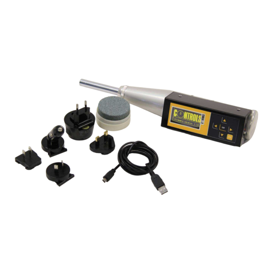
The hammer may be used for comparative testing, referenced against a concrete with known strength or against a concrete verified as conforming to a particular strength class. The test hammer 58-C0181/DGT is supplied complete with: • Multi-voltage/frequency battery charger / with interchangeable plugs compatible with the mote common electrical sockets •... -
Page 6: Icons Appearing In The Manual
This icon indicates a NOTE; please read thoroughly the items marked by this picture. This icon indicates a WARNING message; the items marked by this icon refer to the safety aspects of the operator and/or of the service engineer. 04/02/2015 58-C0181/DGT Rev. 2 EN... -
Page 7: Manual Revision History
Manuale di Istruzioni Instruction Manual Manual revision history Revision/Date Change description Rev. 1 Manual release 15 January 2015 • Rev. 2 Updated declaration of conformity • 04 February 2015 Re-phrased chapter 2.2 58-C0181/DGT Rev. 2 EN 04/02/2015... -
Page 8: Symbols Used
Instruction Manual Symbols used In this manual and on the equipment itself, apart from the symbols indicated on the control panel, the following icons are also used: Symbol Description Dangerous voltage Conformity to the CE Directive 04/02/2015 58-C0181/DGT Rev. 2 EN... -
Page 9: Intended Use And Improper Use
Never use the machine for reasons other than those for which it was designed and manufactured. Any other use of the machine is to be considered improper, not foreseen and hence dangerous. CONTROLS will not be responsible for improper use of the machine. 58-C0181/DGT Rev. 2 EN 04/02/2015... -
Page 10: Safety Information
Safety information WARNING: Please read this chapter thoroughly. CONTROLS designs and builds its devices complying with the related safety requirements; furthermore it supplies all information necessary for correct use and the warnings related to use of the equipment. CONTROLS will not to be held responsible for: •... - Page 11 The present menu is reserved to CONTROLS technical personnel. This procedure shall not be activated unless specifically authorized by the CONTROLS technical personnel. CONTROLS will not be held responsible for damages caused by the unauthorized use of these functions. This will also void the warranty.
-
Page 12: Environmental Risks And Disposal
The correct disposal of this product and the subsequent treatment encourages the manufacture of products using re-cycled materials and limits the environmental impact of the product caused by improper disposal. Improper disposal of the product is subject to penalties as foreseen by the local regulations. 04/02/2015 58-C0181/DGT Rev. 2 EN... -
Page 13: Ce Declaration
Manuale di Istruzioni Instruction Manual CE declaration This page shows a copy of the CE declaration. The original is supplied with the equipment as a separate document. 58-C0181/DGT Rev. 2 EN 04/02/2015... -
Page 14: Description
Refer to the next pictures to identify the main parts of the equipment: Fig. 2-1 Description 6-key keyboard 128x64 pixel display Micro USB port ON/OFF switch Cable for power supply and USB connection to PC Multi-voltage/frequency battery charger Grinding stone Reset button 04/02/2015 58-C0181/DGT Rev. 2 EN... -
Page 15: Working Prenciple
Manuale di Istruzioni Instruction Manual Working prenciple With the new digital rebound hammer 58-C0181/DGT the rebound number is calculated with an innovative technology taking into account the anvil speed before and after the impact. This new working principle is equivalent to the traditional measurement of maximum spring length after the impact, but it provides the following benefits: •... -
Page 16: Main Characteristics
Verification of compliance with the standard in use • Battery charger multi-voltage / multi-frequency: 110-240V / 50-60Hz / 1Ph • Battery charge time: 4 hours. We recommend charging the battery even in case of limited use or after prolonged inactivity. 04/02/2015 58-C0181/DGT Rev. 2 EN... -
Page 17: Identification Plate
Manuale di Istruzioni Instruction Manual Identification plate The identification plate is located on the rear side of the isntrument. Fig. 2-2 58-C0181/DGT Rev. 2 EN 04/02/2015... -
Page 18: Commands And Controls
Manuale di Istruzione Instruction Manual Commands and controls This chapter describes the commands and controls of the equipment. Use the following buttons to move among the different menus: ▲ • to select the previous item in the menu ▼ •... -
Page 19: Technical Specifications
Manuale di Istruzioni Instruction Manual Technical specifications Main characteristics Product Digital Concrete Hammer CONTROLS Cernusco s/N (MI) Italy Manufacturer Product code 58-C0181/DGT Power supply voltage 110-240V / 50-60Hz / 1Ph Frequancy 50/60 Hz Method of power entry External multirange charger with dedicated cable... -
Page 20: Use Of The Equipment
This chapter describes the operator’s interface and the execution of a test. WARNING: We recommend the operator to perform the checks listed in the Maintenance section at the beginning of each working session. If you encounter anomalies, notify your authorized technicians 04/02/2015 58-C0181/DGT Rev. 2 EN... -
Page 21: Charging The Batteries
LED next to the USB port will remain on. Normally the charge takes about 4 hours. Charge the battery when the ambient temperature is between 10 ° C and 40 ° C. The battery status is shown in the upper right of the screen. Fig. 3-2 58-C0181/DGT Rev. 2 EN 04/02/2015... - Page 22 (this parameter is clearly subordinate to the type of use). NOTE: The batteries have a small leakage current, therefore we recommend to recharge them periodically (e.g. once a month), even if the instrument remains unused. 04/02/2015 58-C0181/DGT Rev. 2 EN...
-
Page 23: Turning On The Unit And Menus Description
Turn ON the instrument via the ON/OFF switch on the side panel (Ref. 4 in chapter 2.1), a yellow dot denotes the ON position of the switch. The display will show a screen with CONTROLS logo and the firmware version of the unit: Fig. -
Page 24: Unit Menu
The desired unit is selected when you press the ESC key to return to the MAIN MENU. Fig. 3-5 3.2.2 STRENGTH menu Allows you to set various parameters for the calculation of the estimate of compressive strength from the rebound index. Fig. 3-6 This menu contains the following items in turn. 04/02/2015 58-C0181/DGT Rev. 2 EN... -
Page 25: Conversion Curve Menu
Up to 6 fully customizable curves are available: • 4 curves (called USER 1-4) that are based on the third degree polonomial, where it is possible to set the coefficients A, B, C and D. Fig. 3-8 58-C0181/DGT Rev. 2 EN 04/02/2015... - Page 26 The age of the concrete being tested is a further correction coefficient that takes into account other aspects, such as the humidity, freely interpretable by the user of the instrument. 04/02/2015 58-C0181/DGT Rev. 2 EN...
-
Page 27: Menu Specimen Shape Factor
It is possible to select the type of factor by choosing it from the list and confirm with ENT, and it can also be input through the numerical keypad that appears on the screen You can also change the numerical value through the numerical keypad: Fig. 3-11 58-C0181/DGT Rev. 2 EN 04/02/2015... -
Page 28: Age Factor Menu
The current value can be changed or reset directly to the default value (1.0). Fig. 3-12 • EDIT: it allows entering a coefficient • SET = 1 : to reset the factor to 1. 04/02/2015 58-C0181/DGT Rev. 2 EN... -
Page 29: Correction Factor Menu
The current value can be changed or reset directly to the default value (1.0). Fig. 3-13 • EDIT: it allows entering a coefficient • SET = 1 : to reset the factor to 1. 58-C0181/DGT Rev. 2 EN 04/02/2015... -
Page 30: Standard Menu
If more than 20% of all readings differ from the median by more than 6 units, the entire set of readings shall be discarded". NOTE: The test hammer 58-C0181/DGT is equipped with an internal inclinometer and therefore does not require correction for the test angle. ASTM C805: “9.1 Discard readings differing from the average of 10 readings by more than 6 units and... -
Page 31: User Menu
EN 12504-2 standard (6 units). NUMBER OF READINGS: Allows setting the number of rebounds of the customized test set that will be considered for the calculation method above selected. Fig. 3-17 58-C0181/DGT Rev. 2 EN 04/02/2015... -
Page 32: Test Menu
Allows performing a single measurement and will not take into account the test method previously selected. The following screen will be shown after selecting this option: Fig. 3-19 The instrument is now ready to perform the test. After the test, the following screen will be shown: Fig. 3-20 04/02/2015 58-C0181/DGT Rev. 2 EN... -
Page 33: Set Of Measurements Menu
Fig. 3-21 • STANDARD • CONV. CURVE • SHAPE • AGE FACTOR • CORRECTION FACTOR. Press ENT to show the following screen: Fig. 3-22 58-C0181/DGT Rev. 2 EN 04/02/2015... - Page 34 Press ENT again to save the set of measurements and the relevant results. Pressing ESC the instrument allows adding additional rebound measurements before saving it. Fig. 3-25 All information of a measuring set are saved into the memory of the instrument under the record number indicated. 04/02/2015 58-C0181/DGT Rev. 2 EN...
-
Page 35: Memory Menu
► ◄ The buttons allow scrolling the list faster. Selecting of the measurement sets and pressing ENT, the list of possible actions appears on the screen: Fig. 3-27 58-C0181/DGT Rev. 2 EN 04/02/2015... -
Page 36: View
Allows erasing the selected set of measurements. Confirmation is requested before proceeding. Fig. 3-29 3.2.5.3 ERASE ALL Allows erasing ALL the set of measurements stored in the memory. Confirmation is requested before proceeding. Erased measurements cannot be restored. Fig. 3-30 04/02/2015 58-C0181/DGT Rev. 2 EN... -
Page 37: Service Menu
The language selected from those available is used after the restart of the hammer. Use the ESC key to keep the current selection. Fig. 3-32 3.2.7.2 KEYBOARD SOUND Enables/disabile the tone when pressing a button of the keyboard. Press ENT to confirm. Fig. 3-33 58-C0181/DGT Rev. 2 EN 04/02/2015... -
Page 38: Date And Time
• DAY • MONTH • YEAR • HOURS • MINUTES • SECONDS Press ESC to select the next parameter to set. Fig. 3-34 At the end, it requires confirmation to set the clock. Fig. 3-35 04/02/2015 58-C0181/DGT Rev. 2 EN... -
Page 39: Test Execution
Any plaster or coating covering the concrete should be removed as a first step. Slightly uneven surfaces caused by wooden forms can be removed with the carborundum stone that is supplied with the instrument (Ref. 7 del in chapter 2.1). Fig. 3-36 58-C0181/DGT Rev. 2 EN 04/02/2015... -
Page 40: Uso Of The Test Hammer
Place the rod of the hammer on the surface of the site to be examined so that the same is orthogonal to the surface as possible. The instrument is equipped with an inclinometer that detects the tilt Fig. 3-37 04/02/2015 58-C0181/DGT Rev. 2 EN... - Page 41 STANDARD (refer to chapter 3.2.3), respecting the times indicated NOTE: If you do not respect the waiting time specified at step 7 above, the inclinometer measures will be inaccurate and consequently the results provided by the instrument will not be reliable 58-C0181/DGT Rev. 2 EN 04/02/2015...
-
Page 42: Pc Connection
Load the CD into the drive of the PC. In case the installation does nota start automatically, run the file SETUP on the CD; next screen will be shown. Fig. 3-40 Press OK to proceed. Fig. 3-41 04/02/2015 58-C0181/DGT Rev. 2 EN... - Page 43 Click on the icon to proceed. Fig. 3-42 The installation will proceed automatically and the following screen will be shown at the end. Fig. 3-43 The installer of the program had created an to run it. 58-C0181/DGT Rev. 2 EN 04/02/2015...
-
Page 44: Use Of The Software Program C0181/Dgt Manager
Connect the test hammer to the PC using the USB cable provided and turn the instrument ON. The status on the PC screen will be CONNECTED: Connected Fig. 3-45 The following tools are available on the toolbar: Fig. 3-46 04/02/2015 58-C0181/DGT Rev. 2 EN... -
Page 45: Download Measuremet Menu
Conversion curve: conversion curve selected for the test session • Compressive strength: value automatically estimated by the instrument • Shape factor: selected coefficient • Age factor: always set to 1. Not available at the moment • Correction factor: selected coefficient. 58-C0181/DGT Rev. 2 EN 04/02/2015... -
Page 46: Date And Time Update Menu
Selecting the icon allows synchronizing the clock of the instrument with the clock of the PC. 3.4.2.4 SAVE menu Selecting the icon allows saving the test data stored in the instrument in a file (.csv format). 04/02/2015 58-C0181/DGT Rev. 2 EN... -
Page 47: Open Menu
Selecting the icon allows opening a .csv file previosuly created. 3.4.2.6 GENERATE REPORT menu Selecting the icon allows creating a test report, with all test data in tabular format (use web page format or text format). Fig. 3-49 58-C0181/DGT Rev. 2 EN 04/02/2015... -
Page 48: Firmware Update Menu
The present menu is reserved to CONTROLS technical personnel. This procedure shall not be activated unless specifically authorized by the CONTROLS technical personnel. CONTROLS will not be held responsible for damages caused by the unauthorized use of these functions. This will also void the warranty. -
Page 49: Maintenance
WARNING: Failing to perform the recommended maintenance actions or maintenance performed by unauthorized people can void the warranty. CONTROLS will not be responsible for maintenance and service actions performed by unauthorized people. WARNING: Avoid pouring water, even accidentally, or other liquids into the device, as this could cause short circuits. -
Page 50: Preventive Maintenance
Weekly Cleaning of the mechanical parts Authorized service After approx. 2000 strikes (see chapter 4.3) engineer Replacement of the batteries Authorized service When necessary (e.g. The engineer maximum duration of the battery charge decreases drastically) 04/02/2015 58-C0181/DGT Rev. 2 EN... -
Page 51: Service Menu
FAST, speed higher than the expected range (higher than 110% of the reference speed). When the speed is outside the expected range, the difference in percentage with respect to the expected range will be shown. Refer to the CONTROLS service department in case anomalous results are obtained. 58-C0181/DGT Rev. 2 EN 04/02/2015... -
Page 52: Anvil Check Menu
At the end the display will show the result of the test. Fig. 4-4 Fit the instrument rod into the calibration anvil to take the measurements. Fig. 4-5 04/02/2015 58-C0181/DGT Rev. 2 EN... -
Page 53: Tilt Sensor Check Menu
It also shows the voltage of the internal battery. Fig. 4-6 4.2.4 RESET TO FACTORY menu Allows you to reset all configuration parameters to their default values. Parameters involved are form factors, curve coefficients and corrective factors for the calculation of the strength. 58-C0181/DGT Rev. 2 EN 04/02/2015... -
Page 54: Cleaning Of Mechanical Parts
(13) at the other end. 3. Clean the parts using thinner or gasoline (no trichlorethylene), dry with compressed air and then lubricate the rod of the striker with a light coat of oil. Fig. 4-7 04/02/2015 58-C0181/DGT Rev. 2 EN... -
Page 55: Diagnostics & Troubleshooting
WARNING: Refer to qualified service organization authorized by CONTROLS to carry out service and maintenance procedures. CONTROLS has not to be held responsible for damages to the equipment and/or injuries to personnel in case the above is not strictly followed. -
Page 56: Troubleshooting
• Disconnect the battery charger dropped, etc.) • Turn ON the instrument via its switch. The maximum duration Exceeded the maximum number of Contact CONTROLS service of the battery charge battery recharge cycles or defective department. decreases dramatically batteries 04/02/2015 58-C0181/DGT Rev. 2 EN... - Page 57 Manuale di Istruzioni Instruction Manual Notes: 58-C0181/DGT Rev. 2 EN 04/02/2015...
- Page 58 Manuale di Istruzione Instruction Manual Notes: 04/02/2015 58-C0181/DGT Rev. 2 EN...
- Page 59 Manuale di Istruzioni Instruction Manual Notes: 58-C0181/DGT Rev. 2 EN 04/02/2015...
- Page 60 Manuale di Istruzione Instruction Manual Notes: 04/02/2015 58-C0181/DGT Rev. 2 EN...
Need help?
Do you have a question about the 58-C0181/DGT and is the answer not in the manual?
Questions and answers