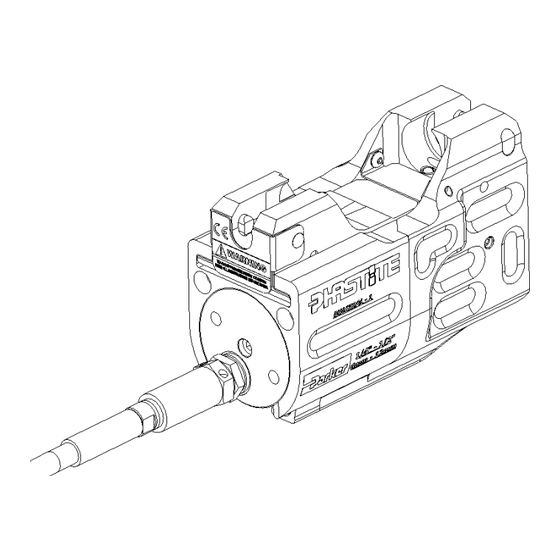
Summary of Contents for Parker Phastite PH-8-HANDTOOL
- Page 1 ASSEMBLY INSTRUCTIONS PH-8-HANDTOOL / PH-8-BENCHTOOL PH-16-BENCHTOOL PH-8-HANDTOOL / PH-8-BENCHTOOL / PH-16-BENCHTOOL Operating Instructions PKLPAI-8-16 Page 1 of 10...
- Page 2 1.0 ASSEMBLY INSTRUCTIONS 1.1 Tool Selection: PH-8-HANDTOOL / PH-8-BENCHTOOL The „PH-8-HANDTOOL‟ and „PH-8-BENCHTOOL‟ Phastite Assembly Tools are suitable for the following sizes of Phastite product only, and must not be used for any other application: Metric Phastite Permanent Connectors for 6mm, 8mm,10mm and 12mm O.D. tube. Inch Phastite Permanent Connectors for 1/4”, 3/8”...
- Page 3 1.3 Jaw Insert assembly / disassembly: Ensure that the correct Jaw Inserts have been selected for the size and type of Phastite connector to be assembled, and jaw (see section 1.2). Fixed Jaw Moving Jaw Moving Jaw Fixed Jaw 1.3.1 PH-8-HANDTOOL / PH-8-BENCHTOOL 1.3.1.1 Assembly.
- Page 4 1.5 Adequate tube insertion. Adequate tube insertion is essential. To achieve this, a Phastite Tube Marker should be used. To use the Phastite Tube Marker: Insert the tube into the Tube Marker. Ensure the tube is against the bottom of the bore (use the inspection hole to verify). While holding the tube, push and twist the Tube Marker one third of a turn.
- Page 5 Parker Phastite Connectors are supplied completely assembled and disassembly of the collar should not be attempted. Insert the tube into the Parker Phastite Connector, ensuring that adequate tube insertion is achieved, see 1.5 for details. Align the Phastite Connector into the tool ensuring that the Connector is orientated to the appropriate jaw insert, see 1.2 for details.
- Page 6 Parker Phastite Connectors are supplied completely assembled and disassembly of the collar should not be attempted. Insert the tube into the Parker Phastite Connector, ensuring that adequate tube insertion is achieved, see 1.5 for details. Align the Phastite Connector into the tool ensuring that the Connector is orientated to the appropriate jaw insert, see 1.2 for details.
- Page 7 1.8.3 Phastite Termination Connectors. Parker Phastite Termination Connectors are supplied completely assembled. The Phastite connector must be disassembled so that the body is separated from the termination end assembly. To do this, loosen the swivel nut from the Phastite body.
- Page 8 1.8.5 PH-16-BENCHTOOL In order to facilitate the assembly of complex tube runs the uppermost cylinder of the PH-16-BENCHTOOL can be removed for access purposes. To remove and reinstall the upper cylinder and arm it is first necessary to activate the tool. This will compress all 3 cylinders. Continue to activate the tool until the moving jaw has moved by approximately ½”...
-
Page 9: Safety Guide
Parker cannot be responsible for damage or injury resulting from unsafe product use, lack of maintenance or incorrect product and/or system operation. Contact Parker when in doubt as to the safety precautions and operations. If you have never been trained on high-pressure hydraulic safety, consult your distribution or service centre for a hydraulic safety course. - Page 10 3.5 Physical Damage: WARNING: Immediately replace worn or damaged parts by genuine Parker parts. Phastite assembly equipment is manufactured from extreme service materials. Standard grade parts will break causing personal injury and property damage. Parker Phastite parts are designed to fit properly and withstand high loads.


Need help?
Do you have a question about the Phastite PH-8-HANDTOOL and is the answer not in the manual?
Questions and answers