Table of Contents
Advertisement
Quick Links
Advertisement
Table of Contents

Summary of Contents for Parker PHK
- Page 1 PHK User Manual Hardware Manual Effective: November 2021...
-
Page 2: Publication History
The user must analyze all aspects of the application, follow applicable industry standards, and follow the information concerning the product in the current product catalog and in any other materials provided from Parker or its subsidiaries or autho- rized distributors. -
Page 3: Safety Symbols
Contact the manufacturer if there is anything you are not sure about or if you have any questions regarding the product and its handling or maintenance. The term "manufacturer" refers to Parker Hannifin Corporation. Safety Symbols The following symbols are used in this document to indicate potentially hazardous situations: Danger! Risk of death or injury. -
Page 4: Construction Regulations
Before performing any work on the hydraulics control electronics, ensure that The machine cannot start moving Functions are positioned safely The machine is turned off The hydraulic system is relieved from any pressure Supply voltage to the control electronics is disconnected PHK User Manual... - Page 5 About the PHK Keypads The PHK family of CAN Based keypads are general purpose user interface keypads suitable for a wide range of outdoor, rugged application on mobile machinery applications. By incorporating these push button keypads into mobile machinery, an extra dimension of operator interface and control can be added to mobile machinery.
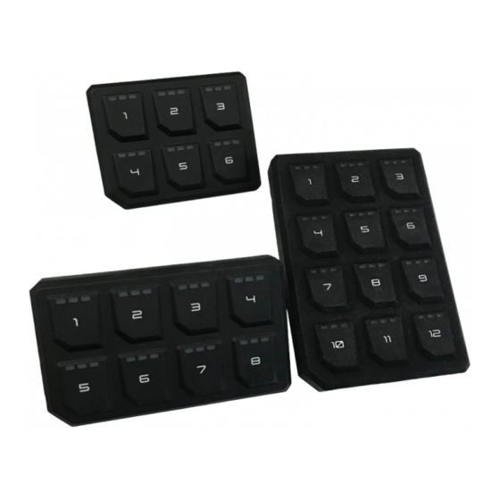
- Page 6 Sizes The PHK Keypads come in three sizes: 2x3, 2x4 and 3x4 buttons, with CAN interface and indicator LEDs. 2X3 Keypad 2X4 Keypad PHK User Manual...
- Page 7 Sizes 3X4 Keypad PHK User Manual...
-
Page 8: Specifications
Auto detection for 250/500 Kbps. Connectors and Pinouts The connector on the rear panel for the PHK Keypads are Deutsch DT06 Series Connectors The pins in the Deutsch DT06 connectors connect to power and CAN. The following tables show the pinouts for each connector:... - Page 9 Communication The connector The PHK keypads support CAN bus communication. The default protocol is SAE J1939 format. The PHK have 1 CAN port. The default PHK CAN messages are shown below Source Address PHK12: 0xC0 PHK6: 0xC1 PHK8:0xC2 Auxiliary Input/Output - Status #1...
- Page 10 LED #26 Key 9 - Center 3865 LED #27 Key 9 - Right 3866 LED #28 Key 10 - Left 3867 LED #29 Key 10 - Center 3868 LED #30 Key 10 - Right 3869 Not Used 3870 Not Used 3871 PHK User Manual...
- Page 11 3891 Not Used 3892 Not Used 3893 Not Used 3894 Not Used 3895 Not Used 3896 Not Used 3897 Not Used 3898 Not Used 3899 Not Used 3900 Not Used 3901 Not Used 3902 Not Used 3903 PHK User Manual...
- Page 12 © 2021 Parker Hannifin Corporation Manual PHK_ 09/2021 Parker Hannifin Corporation Electronic Controls Division 850 Arthur Avenue Elk Grove Village, IL 60007 USA Tel: 800 221 9257 Web: www.parker.com/ecd...


Need help?
Do you have a question about the PHK and is the answer not in the manual?
Questions and answers