Advertisement
Quick Links
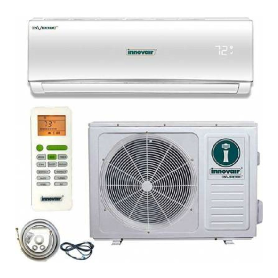
pÜre
HEAT PUMP SYSTEM
Service & Technical
Manual
• The information contained in the manual is intended for use by a qualified service technician
familiar with safety procedures and equipped with the proper tools and test instruments
• Installation or repairs made by unqualified persons can resu t in hazards to you and others.
• Failure to carefully read and follow all instructions in thi manual can result in equipment
malfunction, property damage, personal injury and/or death.
• This service is only for service engineer to use
PIN09H1V51
PIN09H2V51
PIN12H1V51
PIN12H2V51
PIN18H2V51
PIN24H2V51
Advertisement

Related Manuals for innovair PURE PIN09H1V51


Summary of Contents for innovair PURE PIN09H1V51
- Page 1 pÜre HEAT PUMP SYSTEM Service & Technical Manual PIN09H1V51 PIN09H2V51 PIN12H1V51 PIN12H2V51 PIN18H2V51 PIN24H2V51 • The information contained in the manual is intended for use by a qualified service technician familiar with safety procedures and equipped with the proper tools and test instruments •...
- Page 2 Service Manual Contents...
-
Page 3: Operation And Maintenance
When the unit is not to be used for an extended time, Innovair service center. w w w . i n n o v a i r . c o m... -
Page 4: Symbols In This Use And Care Manual Are Interpreted As Shown Below
Service Manual Symbols in this Use and Care Manual are interpreted as shown below. Grounding is essential. Be sure not to do. Warning: Incorrect handling could ºPay attention to such a situation. cause a serious hazard,... - Page 5 Service Manual w w w . i n n o v a i r . c o m...
-
Page 6: Preparation Before Use
Service Manual Preparation before use Note refrigerant of the appliance is R41 A.Otherwise, chemical composition of refrigerant (R410A) inside the system may change and thus affect performance of the air conditioner. pressure of the tube is very high, so be sure to be careful when you install and repair the appliance. - Page 7 Service Manual w w w . i n n o v a i r . c o m...
- Page 8 Service Manual...
- Page 9 Service Manual Model PIN09H1V51 PIN12H1V51 PIN09H2V51 PIN12H2V51 PIN18H2V51 PIN24H2V51 Type Heat Pump Inverter Heat Pump Inverter Heat Pump Inverter Heat Pump Inverter Heat Pump Inverter Heat Pump Inverter Control type Wireless Remote Wireless Remote Wireless Remote Wireless Remote Wireless Remote Wireless Remote Wifi Power supply...
- Page 10 Service Manual...
- Page 11 Service Manual w w w . i n n o v a i r . c o m...
- Page 12 Service Manual...
- Page 13 Service Manual w w w . i n n o v a i r . c o m...
- Page 14 Service Manual...
- Page 15 Service Manual w w w . i n n o v a i r . c o m...
- Page 16 Service Manual...
- Page 17 Service Manual w w w . i n n o v a i r . c o m...
- Page 18 Service Manual...
- Page 19 Service Manual w w w . i n n o v a i r . c o m...
- Page 20 Service Manual...
- Page 21 Service Manual w w w . i n n o v a i r . c o m...
- Page 22 Service Manual...
- Page 23 Service Manual w w w . i n n o v a i r . c o m...
- Page 24 Service Manual...
- Page 25 Service Manual w w w . i n n o v a i r . c o m...
- Page 26 Service Manual...
-
Page 27: Eeprom Fault
Service Manual Error Code Display Reasons E1 or E2 The sensor connection terminal is loose or not plugged in The indoor motor connection terminal is loose or not plugged in The outdoor pipe sensor connection terminal is loose or not plugged in The outdoor ambient sensor connection terminal is loose or not plugged in Outdoor disrchare pipe sensor connection terminal is loose or not plugged in Indoor / Outdoor Communication Issue... - Page 28 Service Manual...
- Page 29 Service Manual w w w . i n n o v a i r . c o m...
- Page 30 Service Manual...
- Page 31 Service Manual w w w . i n n o v a i r . c o m...
- Page 32 Service Manual...
- Page 33 Service Manual w w w . i n n o v a i r . c o m...
- Page 34 Service Manual...
- Page 35 Service Manual w w w . i n n o v a i r . c o m...
- Page 36 Service Manual...
- Page 37 Service Manual w w w . i n n o v a i r . c o m...
- Page 38 Service Manual...
- Page 39 Service Manual Part No. Part Name Q’ty 41106-002054 Front Panel 42008-000039 Air Filter 41106-002375 Face Frame 41211-000077 Electrical Box Cover 31102-000085 Display PCB 42003-000001 Display PCB Box 92011-003149 Evaporator 41108-000066 Screw Cover 42004-000001 Cross Fan 42007-000001 Bearing Mount 22001-000307 Indoor Motor 41101-000242 In And Out Pipe Fixer 42003-000051...
- Page 40 Service Manual Air Conditioner Service Manual Outdoor Unit (BGR00) Part No. Part Name Q’ty 42011-000185 Grille 41207-000040 Top Cover 92011-000804 Condenser 41203-000047 Outdoor Motor Supporter 22001-000049 Outdoor Motor 42004-000103 Propeller Fan 41205-000120 Left grille supporter 41206-000059 Front Plate 42011-000041 Fan Guard 92014-000142 Compressor 92008-000208...
- Page 41 Service Manual Part No. Part Name Q’ty 41106-002054 Front Panel 42008-000039 Air Filter 41106-002375 Face Frame 41211-000077 Electrical Box Cover 31102-000085 Display PCB 42003-000001 Display PCB Box 92011-003149 Evaporator 41108-000066 Screw Cover 42004-000001 Cross Fan 42007-000001 Bearing Mount 22001-000267 Indoor Motor 41101-000242 In And Out Pipe Fixer 42003-000051...
- Page 42 Service Manual Part No. Part Name Q’ty 42011-000184 Grille 41207-000029 Top cover 92011-000706 Condenser 41203-000055 Outdoor motor supporter 22001-000049 Outdoor motor 42004-000107 Propeller fan 41205-000133 Left grille supporter 41206-000052 Front plate 42011-000038 Fan guard 92014-000142 Compressor and accessories 92008-000209 4-way valve 92007-000969 4-way valve assembly 41202-000216...
- Page 43 Service Manual Part No. Part Name Q’ty 41106-002088 Front Panel 42008-000001 Air Filter 41106-002351 Face Frame 41211-000079 Electrical Box Cover 31102-000085 Display PCB 42003-000001 Display PCB Box 92011-003113 Evaporator 41108-000066 Screw Cover 42004-000002 Cross Fan 42007-000001 Bearing Mount 22001-000240 Indoor Motor 41101-000224 In And Out Pipe Fixer 42003-000045...
- Page 44 Service Manual Part No. Part Name Q’ty 42011-000168 Grille 41207-000033 Top Cover 92011-000757 Condenser 41203-000052 Outdoor Motor Supporter 22001-000096 Outdoor Motor 42004-000104 Propeller Fan 41205-000119 Left grille supporter 41206-000057 Front Plate 42011-000040 Fan Guard 92014-000318 Compressor 92008-000207 4-way Valve 92007-000971 4-way Valve Assembly 41202-000252 Base...
- Page 45 Service Manual Part No. Part Name Q’ty 41109-000028 Installation Plate 41199-002746 Base 42004-000042 Cross Fan 42007-000001 Bearing Mount 41101-000251 Bearing Mount Cover 92011-003138 Evaporator 41103-000050 Water Drainage Assembly 41106-002275 Face Frame 41108-000066 Screw Cover 31102-000109 Display PCB 42003-000001 Display PCB Box 42008-000041 Air Filter 41106-002086...
- Page 46 Service Manual Part No. Part Name Q’ty 42011-000187 Grille 41207-000028 Top Cover 92011-000788 Condenser 41203-000046 Outdoor Motor Supporter 22001-000120 Outdoor Motor 42004-000105 Propeller Fan 41205-000117 Left grille supporter 41206-000058 Front Plate 42011-000039 Fan Guard 92014-000474 Compressor 92008-000207 4-way Valve 92007-000983 4-way Valve Assembly 41202-000237 Base...
- Page 47 Service Manual w w w . i n n o v a i r . c o m...
- Page 48 Service Manual...
- Page 49 Service Manual w w w . i n n o v a i r . c o m...
Need help?
Do you have a question about the PURE PIN09H1V51 and is the answer not in the manual?
Questions and answers