Table of Contents
Advertisement
Quick Links
Foshan COXO Medical Instrument Co.,Ltd
Address:BLDG 4,District A,Guangdong New Light Source Industrial Base,
Langsha Luocun,Shishan Town,Naihai District,Foshan City,
Guangdong Province,China
Tel:0086-757-81800058
Fax:0086-757-81800058
E-mail:coxotec@163.com
Http://www.coxotec.com
Wellkang Ltd.
Address:Suite B,29 Harley Street,London W1G9QR,
United Kingdom
Ver2.0
Revision Date:2015-09-30
DENTAL IMPLANT MOTOR SYSTEM
OPERATION MANUAL
Please read this Operation Manual carefully before
using, and filing for future reference.
Advertisement
Table of Contents

Related Manuals for Coxo C-Sailor


Summary of Contents for Coxo C-Sailor
- Page 1 DENTAL IMPLANT MOTOR SYSTEM OPERATION MANUAL Please read this Operation Manual carefully before using, and filing for future reference. Foshan COXO Medical Instrument Co.,Ltd Address:BLDG 4,District A,Guangdong New Light Source Industrial Base, Langsha Luocun,Shishan Town,Naihai District,Foshan City, Guangdong Province,China Tel:0086-757-81800058 Fax:0086-757-81800058 E-mail:coxotec@163.com...
- Page 2 -The Implanted is designed for intermittent operating mode with an operating time of 2 minutes and an idle time • C-Sailor should not be used adjacent to or stacked with other equipment and that if adjacent or stacked use is necessary, the of 10 minutes.
-
Page 3: Package Contents
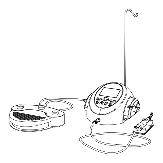
3.Control Unit with an Irrigation Pump Humidity Temperature Atmospheric pressure Between 0-40˚C (32-104˚F) Between10-85%RH Between 700-1060hPa Store Transportation Between -10-55˚C(14-131˚F) Between 10-85%RH Between 500-1060hPa Main Power Switch AC Eletrical Cord ** No moisture condensation in the Control Unit. Connetion socket Fuse Holder ** Using at outside of these limits may cause malfunction. -
Page 4: Foot Control
LCD display on the Control Unit Console 4.Foot Control Forward/Reverse Speed Coolant Flow Level Gear Ratio Program Number GEAR Foot Control Cord and Plug Torque PRG(Program) Button Pedal Progress Bar Pedal Link Indicator N.cm Coolant Solution Flow Volume Button Forward/Reverse Button 100% Speed Control Pedal (1) Coolant Flow Level... -
Page 5: Installation
After the tubes are correctly positioned, close the Pump Cover Fig. 6 5. Installation by turning the Pump Cover Lever to the ‘CLOSE’ position (180 degrees counter-clockwise).(Fig. 6&7) 5-1 Connecting the Motor Cord Fig. 1 RELEASE CLAMP Plug the Motor cord into the motor interface of the main unit, fasten the Fixed nut after that. -
Page 6: Operation
5-7 Compatibility check of Internal Irrigation Nozzle/Drill 6. Operation Internal irrigation nozzles accompanied with this product; is not necessarily fitted into all the drills on the market. Follow the instructions given below for confirmation prior to use.Failure to do so or to fit the internal 6-1 Programming the Micromotor Operation irrigation nozzle into drills may cause a leakage of saline solution, which will result in problems such as rust or The Control Unit can memorize... -
Page 7: Standard Operation
6-2 Standard Operation 7. Cleaning, disinfection, packing and sterilization All standard operational functions can be control at the Foot Control. (1) Turn on the Main Power Switch: The Control Unit is ready to perform the Program. 7-1 Manual cleaning (2) Select the desired program number: Step on the Foot Control PRG (Program) Button and the program •... -
Page 8: Care And Maintenance
8-3 Fuse Replacement 8. Care and Maintenance If the Control Unit does not function, check the fuses ( Fuse Box Fig. 15 lock located on the rear of the Control Unit ). To access the Fuse, Fuse 8-1 Protection Circuit use a pointed tool push on the fuse locking latch and the drawer will spring open.(Fig. -
Page 9: Specifications
9. Specifications 11. Disposing Product Consult with dealer from whom you purchased it about waste disposal. 9-1 Control Unit Model C-Sailor Power Supply Voltage AC230V 12. Symbols Frequency 50Hz Power Consumption 120VA The EU directive 93/42/EEC was applied in the design and production of this medical device.
Need help?
Do you have a question about the C-Sailor and is the answer not in the manual?
Questions and answers