
Related Manuals for Coxo CX235


Summary of Contents for Coxo CX235
- Page 1 CONTRA ANGLE MODEL:CX235 Please read this operation Manual carefully and file for future reference.
-
Page 2: Technical Specifications
Preface Thanks for purchasing our dental Contra angle! In order to fully exert the function of this equipment, safely and effectively use this equipment, please read this instruction carefully before using , and please keep this manual well for reference anytime. Under regulations'request, we have been committed to the optimization of our product, this may cause some parts of change, when you find the product appears some difference from description in the... - Page 3 • Please read this operation manual carefully before use and file it for future reference . • This product is spcialized for stomatology treatment abnormal,don’t use it in other ways. • This product is only for doctors. • Every time you use it,please check first.If find anything unnormal,stop using immediately,and contact your supplier or our after-sales center for details.
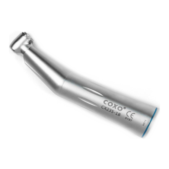
- Page 4 Product Composition Inner channel1:1 Φ2.35 Φ2.35 Push button Push button Φ2.35 Optic fiber LED bulb Push Push button button Generator inside Optic fiber Optic fiber contra angle LED contra angle with generator contra angle (CX235-1B) (CX235-1C) (CX235-1E) (CX235-1G) Fig. 1...
-
Page 5: Cartridge Replacement
•Inner channel contra angle low speed handpiece ; •Burs:for CA burs Φ2.35; •Max.speed of contra angle:40000rpm Cartridge Replacement Loosen the small screw on the curving part ,move the head cover and remove the transmission gear[Fig.2.1]. Use the attached wrench to remove the cap[Fig.2.2]. Use the bur to push out the cartidge. - Page 6 2. Hold the bending machine and pull out the motor, it will be separated Alignment the groove,contra angle can insert into the air motor[fig.3.3]. Fig.3.1 Contra angle with generator Air motor(CX235-3B) (CX235-1E) Bur size:Ø2.35 1: 1 drive Fig.3.2 Contra angle(CX235-1B) Air motor(CX235-3B) Bur size:Ø2.35...
- Page 7 2.contra angle head technical parameters Model Rotate head CX235CH-1 /2 max.40,000rpm for CA burs Φ2.35 CX235CH-3 /4 max.40,000rpm for CA burs Φ2.35 CX235CH-6 /7 max.40,000rpm for use files CX235CH-13 max.30,000rpm forCA burs Φ2.35 CX235CH-15/16 max.3,000rpm forCA burs Φ2.35 CX235CH-17 max.40,000rpm for CA burs Φ2.35 360°...
- Page 8 2.Special head movement technical parameters Model Rotate head CX235CH-10 90° reciprocating for CA burs Φ2.35/prophylaxis brush CX235CH-11 Up and down movement for CA burs Φ2.35/the crevices knife CX235CH-12 60° reciprocating for use files CX235CH-9 360° reciprocating forCA burs Φ2.35/implant files CX235CH-14 360°...
-
Page 9: Product Composition
Push button Push button Latch plate Latch plate Latch plate for CA burs Φ2.35 for CA burs Φ2.35 for FG burs Φ1.6. for CA burs Φ2.35 for CA burs Φ2.35 CX235C1-2 CX235C1-4 CX235C1-7 CX235C1-13 CX235-1F Fig.2.1 Fig.2.2 Fig.2.3 Fig.2.4 Fig.2.5... - Page 10 mini head Push button Push button Latch plate Latch plate for CA burs Φ2.35 for CA burs Φ2.35 for FG burs Φ1.6. for CA burs Φ2.35 CX235C2-1 CX235C2-3 CX235C2-6 CX235C2-13 18° Φ19.6 Fig.2.6 Fig.2.7 Fig.2.8 Fig.2.8 Φ2.35 Fig.3.1 •External contra angle low speed handpiece--1:1 Direct Drive •Burs:for CA burs Φ2.35 ;...
- Page 11 Mounting of bur 1.Locking pin Open the latch chuck,insert the bur,be sure the quadrate part of the bur aline the proper part in the cartridge then turn the latch chuck back. When remove the bur,open the latch chuck then take out the bur. 2.Push button The fixed method of internal contra low speed handpiece is push button, push the button to the end and then the bur can be get out of head.
- Page 12 Product Composition 4:1 reduction 90° reciprocation up and down rotate movement mini head Push button Prophylaxis Latch plate Latch plate Latch plate 4:1 reduction 4:1 reduction 4:1 reduction CX235C3-1 CX235C3-4 CX235C3-8 CX235C3-13 CX235C3-10 CX235C3-11 Fig.4.3 Fig.4.4 Fig.4.5 Fig.4.6 Fig.4.1 Fig. 4.2...
- Page 13 Mounting of bur 1.Locking pin Open the latch chuck,insert the bur,be sure the quadrate part of the bur aline the proper part in the cartrdge then turn the latch chuck back. When remove the bur,open the latch chuck then take out the bur. 2.Push button The fixed method of internal contra low speed handpiece is push button, push the button to the end and then the bur can be get out of head.
- Page 14 3.Prophylaxis Mounting and Removing the Rubber Cup/Brush Mounting 1)Insert the rubber cup/brush into a screw hole of the handpiece head. 2)Turn rubber cup/brush in a colckwise direction to fix the screw shank. Removing Perform a reverse procedure of Mounting. Turn the Rubber cup/brush way of “Loosen”dirction.
-
Page 15: Mounting And Removing File
Product Composition 10:1 Reduction push button CX235C5-12 18° Φ19.6 Fig.7 hand use file 10:1reduction hand press Mounting and Removing File NOTE: 1-Do not connect or disconnect the handpiece until the drive motor has completely stopped. 2- After the file is locked in place, lightly pull Insert the hand use files out the file to make sure the file Fig. - Page 16 Product Composition 16:1 Reduction External spray nozzle 90° reciprocation up and down Push button movement Push button rotate mini head External spray nozzle Latch Push Latch plate Latch plate plate button CX235C4-4 CX235C4-14 CX235C4-10 CX235C4-11 CX235C4-2 CX235C4-9 CX235C4-13 Fig.8.1 Fig.8.2 Fig.
- Page 17 Mounting of bur 1.Locking pin Open the latch chuck,insert the bur,be sure the quadrate part of the bur aline the proper part in the cartrdge then turn the latch chuck back. When remove the bur,open the latch chuck then take out the bur. 2.Push button The fixed method of internal contra low speed handpiece is push button, push the button to the end and then the bur can be get out of head.
- Page 18 Product Composition 20:1 Reduction External spray nozzle Push MINI head button External Latch plate Latch plate spray nozzle 20:1 20:1 20:1 20:1 reduction reduction reduction reduction CX235C6-9 CX235C6-14 CX235C6-13 CX235C6-19 Fig.10.1 Fig.10.3 Fig.10.4 Fig.10.2...
- Page 19 Mounting and Removing Bur Locking pin Open the latch chuck,insert the bur,be sure the quadrate part of the bur aline the proper part in the cartrdge then turn the latch chuck back. When remove the bur,open the latch chuck then take out the bur. NOTE: 1-Do not connect or disconnect the handpiece until the drive motor has completely stopped.
- Page 20 Mounting the”Y”type water tube Three irrigation methods are available; External, Internal or both External and Internal, depending on tool and operation procedure. External spray nozzle (1) External Spray Nozzle Connect the Irrigation Tube to the External irrigation Tube Spray Nozzle firmly. Fig.
- Page 21 Internal spray nozzle Irrigation tube Irrigation tube “Y” Connector Fig.12.2 Fig.12.3 Fig. 12.4 (4) External and Internal Irrigation together (push button) Only a drill with internal irrigation is used. 1-Connect the ends of the Y-Connector to the External Spray Nozzle and Internal Spray Nozzles refer as detailed in procedures (1) and (2).
- Page 22 Cartridge Replacement 1.1Locking pin Loosen the curving lock section and remove the head from the sheath. Pull out the drive gear assembly from the head.[Fig.13.1] Please cap the wrench on the head'screw and turn counter-clockise. Unscrew and separate the cover.[Fig.13.2] Swing the new cartridge,with its pin aligned in the groove of the head.
- Page 23 (CX235CH-11) Loosen the curving lock section and remove the head from the sheath. Pull out the drive gear assembly from the head.[Fig.14.1] Directly remove the cartridge.[Fig.14.4] Slit Fig. 14.1 Fig.14.2 Fig. 14.3 Fig. 14.4 (CX235CH-10) Fig.14.5 Fig. 14.6 (CX235C6-19) (CX235-1F)
-
Page 24: Push Button
2.Push button Loosen the small screw on the curving part ,move the head cover and remove the transmission gear[Fig.15.1]. Use the attached wrench to remove the cap[Fig.15.2]. Use the bur to push out the cartidge. Insert the new cartridge into handpiece head,being sure the small raised part aligns the groove inside the front of the head,to insure proper fit. - Page 25 Contra angle and motor connections 1. Straightly insert the motor into the connection of contra angle, until you hear a “cracking" sound can be. 2. Hold the bending machine and pull out the motor, it will be separated. Fig. 16.1 Fig.
- Page 26 After daily use,spray lubricant for 1 to 2 seconds by inserting lubricant nozzle all the way into drive air tube. If work heavyly,lubrication should be implemented at noon and afternoon’s after using everyday. Lubricate the head,gear and inside.[Fig.16] When lubricate the head,please open the latch chuck.
- Page 27 Clean-head system 1-Scrub dirt and debris from the handpiece. 2-Stop the handpiece and wipe it dry.If the dirt could not remove from the hole, remove the cartridge and clean by brush. Fig.17 Notice! Use only clean water to maintain the clean head system. Cleaning -bulb Wipe clean the Cellular optical bulb entry point with an alcohol-immersed cotton swab.Remove all debris and oil.
- Page 28 E spray nozzle contra hand Fig. 18...
-
Page 29: Sterilization And Cleaning
Sterilization and cleaning -Steam autoclave is recommended. -Sterilization requirement after using as noted below. -Autoclave Procedure: -Scrub dirt and debris from the handpiece,and wipe clean with alcohic cotton.Do not use a wire brush(Fig.18.4) -Lubricate with SPRAY or Lubricant oil. -Lubrication. -Insert into an autoclave pouch.Seal the pouch. - Page 30 NOTE:After treatment or before autoclave,please do the lubrication. Fig. 18.4 Fig.18.5 STERILE 275°F Fig. 18.6 Fig.18.7 Fig.18.8...
-
Page 31: Troubleshooting
Trouble Shooting Trouble Possible cause Solution Body of straight head or O-ring on the nose of motor Change o-ring contra angle rotates during wears motor running Contra angle chucking with bur but lacth plate fail to be Clean and lubricate, Handpiece fail to rotate fixed in the proper position. -
Page 32: Warranty
Warranty COXO grants the user a 12 months guarantee for its complete product range,except ball bearing(3 months guarantee) from the date of invoice issued, Maintenance over the term of guarantee will be at the customer's charge. COXO will not be responsible for damage or injury resulting from:... - Page 33 Standard Symbols STANDARD SRMBOLS Important notice! Autoclave Transportation and deposited condition Environmental temperature range:-40°C--+50°C;Relative humidiy≤80%; The scope of air pressure:500hPa—1060hPa. +70°C/158°F max. +40°C/40°F min.
- Page 34 Foshan COXO medical instrument Co.,Ltd Address:21 Wufeng Si Road,Foshan,Guangdong,China Wellkang Ltd. Address:SuiteB,29 Harely Street,London W1G9QR,United Kingdom Foshan COXO medical instrument Co.,Ltd TEL:+ 86 757 86174018,86121615 FAX:+86 757 86125200 E-mail:coxotec@163.com Http://www.coxotec.com Rev.D revision Date:2014-8-13...
Need help?
Do you have a question about the CX235 and is the answer not in the manual?
Questions and answers