PAW FC3.10 Assembly, Installation And Operation Instructions
Controller for dhw modules
Hide thumbs
Also See for FC3.10:
- Installation and operation instructions manual (40 pages) ,
- Installation and operation instruction manual (68 pages) ,
- Installation and operation instruction manual (88 pages)
Table of Contents
Advertisement
Quick Links
Advertisement
Table of Contents

Related Manuals for PAW FC3.10


Summary of Contents for PAW FC3.10
- Page 1 PAW GmbH & Co. KG Böcklerstr. 11, 31789 Hameln - Germany Phone: +49-5151-9856-0, Fax: +49-5151-9856-98 E-Mail: info@paw.eu, Web: www.paw.eu Installation and Operation Instructions Controller FC3.10 for DHW modules 2022/07 99E13331xx-mub-en - V08...
- Page 2 Translation of the original instructions PAW GmbH & Co. KG We reserve the right to make technical changes without notice! Böcklerstraße 11 Printed in Germany – Copyright by PAW GmbH & Co. KG 31789 Hameln - Germany 99E13331xx-mub-en - V08 2022/07...
-
Page 3: Table Of Contents
1 General Information Contents General Information ......................7 Scope of these instructions ..................7 Designated use ......................7 Target group ........................ 7 Safety instructions ......................8 Mounting and installation [specialist]] ................9 Installation of the controller................... 9 Establishing the electrical connections ............... 11 Product description and operation .................. - Page 4 1 General Information Service ........................23 Controller ........................23 Hot water ........................24 Functions ........................24 10 General settings ......................25 10.1 Language ........................25 10.2 Date ........................... 25 10.3 Time ........................... 25 10.4 Synchronise date/time ....................25 10.5 Automatic Daylight saving time / Standard time ............25 10.6 Commissioning* ......................
- Page 5 1 General Information 16 Advanced settings ......................32 16.1 Remote control / write protection ................32 16.2 Minimum speed* ......................33 17 Description of function ....................33 17.1 Circulation ........................33 17.2 Stratification (return stratification) ................38 17.3 Modulating hot water temperature ................39 17.4 Comfort function ......................
- Page 6 1 General Information 21.5 Advanced settings* ....................58 22 Functions in the cascade network .................. 58 22.1 Circulation ........................58 22.2 Stratification return ..................... 59 22.3 Comfort function ......................60 22.4 Thermal disinfection ....................60 22.5 Alarm relay ......................... 61 22.6 Parallel relay ......................
-
Page 7: General Information
The maintenance-free controller is exclusively intended for the controlling and monitoring of a PAW domestic hot water module. Improper usage of the controller excludes any liability claims. Only use PAW accessories with the controller. -
Page 8: Safety Instructions
2 Safety instructions 2 Safety instructions The installation and commissioning as well as the connection of electrical components require technical knowledge commensurate with a recognised vocational qualification as a fitter for plumbing, heating and air conditioning technology, or a profession requiring a comparable level of knowledge [specialist]. -
Page 9: Mounting And Installation [Specialist]]
3 Mounting and installation [specialist]] 3 Mounting and installation [specialist]] Installation of the controller NOTICE The following section describes only the installation of the controller. Follow the instructions of each respective manufacturer when installing external components (valves etc.). Do not put the controller into operation in case of any visible damage. 1. - Page 10 3 Mounting and installation [specialist]] WARNING Risk of death by electrocution! Disconnect the controller from the power supply before opening the body. Make sure that the power supply cannot be unintentionally switched on when the body is open. Inputs FriwaMini: Terminal Individual operation mode / Cascade operation mode...
-
Page 11: Establishing The Electrical Connections
3 Mounting and installation [specialist]] Outputs: Terminal Individual operation Cascade operation mode Optional: alarm relay, error relay, Cascade valve reheating, stratification Optional: stratification, alarm relay, Stratification error relay, reheating (Connection at server 1) Primary- / secondary pump Primary- / secondary pump PWM1 Primary pump Primary pump... - Page 12 3 Mounting and installation [specialist]] ATTENTION Danger of damage and malfunction! Connect only components that do not overload the controller inputs and outputs; more Technical data information is provided on the type plate and in the section. NOTICE Any connection polarity may be used for the 1 – 4 signal inputs and outputs. ...
-
Page 13: Product Description And Operation
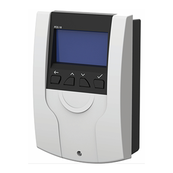
4 Product description and operation 4 Product description and operation View of the controller Display with hydraulic scheme Operating buttons USB service interface (below the front panel) Operating buttons / key combination Description Button Back: goes back to the next higher level or back to the system overview Upwards: navigates upwards in the menu, increases adjustment values... -
Page 14: Display
4 Product description and operation Display Remaining time of Flow rate (VFS V) Flow temperature disinfection (T-FL) Hot water Time with day of temperature (T- the week DHW) Speed of the primary Speed of the pump (PWM 1) Cold water circulation pump temperature (T-CW) (PWM 2) -
Page 15: Symbols
5 Commissioning [specialist] Symbols Symbol Description Three-way valve with flow direction Check box (activated/deactivated) Disinfection active Error message Manual mode Pump Storage tank Thermometer Heat exchanger Modulating hot water temperature active Water withdrawal point USB record active Write protection for remote control via WiFi module, BMS, Modbus Gateway Modbus communication active SYNC... -
Page 16: Language
5 Commissioning [specialist] Language Set the desired menu language. LANGUAGE Deutsch (DE) Polski (PL) English (ENG) Français (FR) Controller type Set the available type of controller. The menu item Single CONTROLLER TYPE controller should be selected if you want to put into Single controller operation only one domestic hot water module. -
Page 17: Automatic Daylight Saving Time / Standard Time
5 Commissioning [specialist] Automatic Daylight saving time / Standard time Activate/deactivate the automatic daylight saving time / standard time When the controller is delivered, this item is activated. Cascade* At this menu item, the operating parameters (switchover point, duration of backup mode) of the domestic hot water modules within a cascade are set. -
Page 18: Finish Without Protocol
5 Commissioning [specialist] 5.11 Finish without protocol Completes the commissioning without a further saving on an external USB flash drive. The settings made during the commissioning can be changed at any time in the corresponding sub menus. After the commissioning is completed, the controller is ready for use. Parameters Meaning Adjustment range... -
Page 19: Menu Settings
6 Menu settings By pressing the operating button ( ), the menu of the controller FC3.10 opens. The menu bar contains multiple submenus in which you can find or modify various settings. The available menu items of the first three levels are shown as a menu tree and will be explained in detail in the following chapters. - Page 20 6 Menu settings Measured/balance values Reports Status Service Controller Nominal temperature Hot water Minimum temperature* Maximum temperature* Circulation Stratification return Modulating hot water temperature Comfort function Disinfection Functions Alarm relay Parallel relay Hygienic flush / protection against blocking Buffer tank* Reheating* Language Date...
- Page 21 6 Menu settings Registration DHCP IP address Internet module Net mask Gateway address DNS address Information Remove data carrier Load settings Save settings Save alarm history Param. Save history Data logging interval Recording type Format data carrier Properties Automatic mode Sensor simulation Relay 1 Automatic/manual mode...
-
Page 22: Status
7 Status 7 Status Status The menu item contains submenus which allow to STATUS look through all measured/balance values, temperatures and flow rates at the sensors, relay states, operating Measured/balance values times, heat quantity, tap performance as well as error Reports messages. -
Page 23: Reports
Automatic/manual mode and which relays and sensors are actuated via the automatic/manual mode. Calibration Controller Display of the current software version and the domestic hot water module which was selected during FC3.10 commissioning. FriwaMini with circulation VERSION 1.0.0 BUILD No. 1909... -
Page 24: Hot Water
8 Hot water 8 Hot water In this menu item, you can make the temperature settings NOMINAL TEMPERATURE for the hot water preparation. 60 °C MIN : 35 MAX : 75 Setting options for the following parameters are available: Nominal temperature: the set hot water temperature which is supposed to be reached at •... -
Page 25: General Settings
10 General settings The following functions are available: Circulation • Stratification return • Modulating hot water temperature • Comfort function • Disinfection • Alarm relay • Parallel relay • Hygienic flush • Buffer tank* • - Reheating* • Description of function. Detailed information in chapter *Settings only visible with installer code (see chapter "User code"). -
Page 26: Commissioning
10 General settings 10.6 Commissioning* Opens the commissioning menu to go through the settings again. *Settings only visible with installer code (see chapter "User code"). 10.7 Software update To update the firmware, a USB flash drive with the new software on it must be connected to the USB port. -
Page 27: Internet Module
Synchronisation of the time with the Internet Additional instructions are enclosed to the Internet module. The following data can be additionally set in the domestic hot water controller FC3.10: 11.1 Registration The registration is required to retrieve data of the domestic hot water module via the Internet and to make settings. -
Page 28: Set Up The Network
The domestic hot water module can be connected to the Building Management System (BMS) via the Modbus interface of the FC3.10 controller. In this menu item, the Modbus transfer parameters such as Baudrate, data bits, stop bits, parity etc. can be set. Detailed information for the setting can be found in chapter 23 "Connection to Building Management System". -
Page 29: Remove Data Carrier
13 USB The following functions can be carried out with a USB flash drive: 13.1 Remove data carrier Safe removal of a USB flash drive from the system in order to avoid data loss before the data are completely saved. 13.2 Load settings If there are controller settings on the USB flash drive, you can export them to the controller in Load settings... -
Page 30: Format Data Carrier
14 Automatic/manual mode 13.8 Format data carrier Formats the USB flash drive. All data will be deleted on the USB flash drive. 13.9 Properties Displays the capacity and the free memory on the USB flash drive. Parameters Meaning Adjustment range Factory setting Remove data carrier Safe removal of the... - Page 31 14 Automatic/manual mode The manual mode has the highest priority. These setting values overwrite the automatic actuating values of the controller. If the controller runs in manual mode, a hand symbol is shown on the display of the system overview. Parameters Meaning Adjustment range...
-
Page 32: User Code
A remote control allows a remote monitoring, data logging and setting of parameters of a domestic hot water module even if you are not nearby the module or the controller. All domestic hot water modules based on the FC3.10 controller allow a remote control which can be realised in different ways: BMS connection (Modbus RTU protocol) •... -
Page 33: Minimum Speed
", " ") if these are Scan Modbus connected to the FC3.10 controller and are put into operation (e.g. " " for MB3.10, see chapter 5.7). If required, this (de)activated function can be protected by a personalised password to avoid modifications (on/off) by third parties. Please store this password on a safe place because the activated function / the password cannot be reset, even if you reset to factory settings. - Page 34 17 Description of function During the first commissioning of the circulation pump, you should specify the following parameters to adapt the operation of the domestic hot water module to the current circulation line: PWM value (0 ... 100 %) for the control of the circulation pump (PWM 2) •...
- Page 35 17 Description of function Operation mode "temperature control" As a temperature sensor for the temperature control, either the cold water sensor (T-CW) or an external temperature sensor can be selected. If the temperature measured at the selected sensor falls below the switch-on temperature, the circulation pump is actuated. If the temperature measured at the selected sensor is higher than the switch-off threshold (switch-on temperature + ΔT Off), the circulation pump is switched off.
- Page 36 17 Description of function Connecting the operation modes You can connect the 3 circulation operation modes with each other in order to adapt the circulation to your needs. The following combinations are possible: Time control + temperature control: The temperature control is only active during the •...
- Page 37 17 Description of function Meaning Adjustment range Factory setting Parameters Circulation active Activate the function On, Off Temperature control Submenu for On, Off settings of the temperature control Switch-on temperature Setting the switch- 35 ... 75 °C 55 °C on temperature ΔT Off ΔT for the 2 ...
-
Page 38: Stratification (Return Stratification)
17 Description of function 17.2 Stratification (return stratification) This function serves to improve the temperature stratification in the storage tank or to avoid a temperature mix. In the return can be considerable temperature differences (for example, with an existing circulation). Therefore, the return is connected to the storage tank via a three-way valve. -
Page 39: Modulating Hot Water Temperature
17 Description of function NOTICE If the three-way valve was not activated in the last 24 hours, it is opened and closed automatically. This prevents that the valve seizes up after a longer downtime. Parameters Meaning Adjustment range Factory setting Stratification return Activate the function On, Off... -
Page 40: Comfort Function
17 Description of function 17.4 Comfort function The comfort function controls the operation of the primary pump when there is no withdrawal and circulation. In order to speed up the start-up process of the module, the flow to the heat exchanger can be warmed up and be maintained on a certain temperature. -
Page 41: Disinfection
17 Description of function 17.5 Disinfection WARNING Danger of scalding due to hot water! If the function is activated, there is the risk of scalding during the defined time window at all withdrawal points! Inform user Make sure to avoid scalding at the installation ... -
Page 42: Alarm Relay
17 Description of function Parameters Meaning Adjustment range Factory setting Disinfection Activate the function On, Off Manual disinfection Manual start of the On, Off disinfection Disinfection temperature Setting the disinfection 60 ... 80 °C 60 °C temperature Duration of disinfection Setting the duration of 10 ... -
Page 43: Parallel Relay
17 Description of function Parameters Meaning Adjustment range Factory setting Alarm relay Activate the function On, Off Relay selection Selection of the relay Relay 1, Relay 2 Inverted Relay function inverted On, Off Pt1000 error Short-circuit / interruption at a On, Off temperature sensor VFS/US error... -
Page 44: Hygienic Flush / Protection Against Blocking
17 Description of function Parameters Meaning Adjustment range Factory setting Parallel relay Activate the function On, Off Relay 1 Submenu to relay 1 Deactivated Status of the relay On, Off Primary pump Connects in parallel to the On, Off primary pump Circulation pump Connects in parallel to the On, Off... -
Page 45: Buffer Tank
17 Description of function Parameters Meaning Adjustment range Factory setting Hygienic flush / protection Activate the On, Off against blocking function Start time Start time of the 0 ... 11:00 p.m. 10:00 a.m. hygienic flush Flush duration Duration of 00:00 ... 10:00 min 05:00 min hygienic flush 17.9 Buffer tank*... -
Page 46: Installation Of The Cascade Controller
/ communication cable. For further details, please refer to the separate operation instructions of the MB3.10 (PAW item no. 1339002). In the following illustration you can see an example of a 4-fold cascade. To connect the two-way... -
Page 47: Installation
18 Installation of the cascade controller 18.1 Installation During the installation, please observe the instructions in chapter 3.1 and 3.2. DANGER Risk to life and limb due to electric shock! Disconnect the controller from the power supply before opening the ... - Page 48 18 Installation of the cascade controller 1. Remove the white front panel of the controller (1). 2. Then, remove the strain reliefs (2). 3. After that, remove the sensor cables of the VFS/US sensors, of the PWM signal and the temperature sensors from the controller circuit board plug connector (3).
- Page 49 18 Installation of the cascade controller Cascade valve (at the left) 3-way valve (at the right) Brown - L (via duo wire end ferrule) Brown - L (via duo wire end ferrule) Black – L (R1) White – L (R2) Blue –...
- Page 50 18 Installation of the cascade controller Pos. 1 Pos. 2 6. For the first and last participant of the Modbus communication, the jumpers must be placed in position 2 (see upper illustration). Place the jumpers as follows: Number of Client Server 1 Server 2 Server 3...
-
Page 51: Initial Commissioning Of The Cascade Controller
18 Installation of the cascade controller If the MB3.10 is meant to be connected as well, plug the jumpers as follows: Number of MB3.10 Client Server 1 Server 2 Server 3 cascade modules Pos. 2 Pos. 1 Pos. 2 Pos. 2 Pos. - Page 52 18 Installation of the cascade controller Now, assign the correct controller types to the other modules. If a controller was marked as a server, the menu items of the commissioning are shortened because the main parameters are set via the client. To complete the commissioning at the servers, confirm COMMISSIONING Finish with protocol...
-
Page 53: Extension Of A Single Controller To A Cascade Network
18.3 Extension of a single controller to a cascade network If you already have a FC3.10 domestic hot water system as a single controller and if you wish to extend it to a cascade network, you first need to enter the installation code. For more information, see chapter 15. - Page 54 19 Menu settings cascade Circulation Stratification return Comfort function Status** Disinfection Hot water Alarm relay Functions Parallel relay Hygienic flush / protection against blocking Buffer tank Reheating Language Date Time Date/time sync. Basic settings** Auto. Daylight saving time/ standard time Commissioning Software update** Display**...
-
Page 55: Submenu Cascade At The Client
20 Submenu Cascade at the client 20 Submenu Cascade at the client The main setting options were already described in the chapters 7-17. The menu item "Modbus Gateway MB3.10" is described in detail in chapter 23 "Connection to Building Management Cascade System"... -
Page 56: Switchover Point Off
20 Submenu Cascade at the client 20.3 Switchover point OFF* Here you can define the threshold for the minimum flow rate when the active module is switched off and the cascade valve closes. The percentage refers to the maximum flow rate of the active modules. -
Page 57: Submenus At The Server
21 Submenus at the server Parameters Meaning Adjustment range Factory setting Cascade switchover Overview for the points minimum flow rate when a module is activated or switched off. Switchover point ON Threshold for the 70 ... 100 % 80 % minimum flow rate when the next module is activated... -
Page 58: Usb
22 Functions in the cascade network 21.3 USB If a USB flash drive is connected to the controllers, you must make the corresponding settings Eject memory separately at the different modules. Before removing a USB flash drive, confirm at the controllers in order to ensure the optimal functioning of the USB flash drive. 21.4 Automatic / manual mode Setting options for the automatic/manual mode are made for each controller, see chapter 14. -
Page 59: Stratification Return
22 Functions in the cascade network There is always only one circulation pump within the entire cascade. If this function is activated, it only appears on the client display. The client display is shown as in the display view in chapter 17.1. -
Page 60: Comfort Function
Server 1 - sensor 2. in the return line. The external sensor can be connected to the input The measured values of the external sensors can be read at the SV1- FC3.10 controller at Menu - Status - Measured values - Sensors. -
Page 61: Alarm Relay
22 Functions in the cascade network When a disinfection starts, all cascade valves are opened. This means, all modules carry out the disinfection at the same time. The disinfection is logged as "successful" when, during the duration of the disinfection, the temperature at the cold water inlet (with circulation) or hot water outlet (without circulation) has Disinfection OK exceeded the temperature (disinfection temperature - 5 K) for the defined time... -
Page 62: Connection To Building Management System
23.1 Single domestic hot water module Connection of the controller to BMS The domestic hot water modules with the FC3.10 controller have the great advantage that the Modbus interface already exists at the controller. No additional hardware is required to realise the BMS connection. - Page 63 23 Connection to Building Management System If the FC3.10 controller is operated as the physical first / last device in the Modbus network, a termination via a jumper is required. For this, the jumper must be plugged at the right side of...
-
Page 64: Cascade
A Friwa Cascade (up to 4 modules) can, as well as an single module, only be connected to the BMS as a bus participant. For this, the MB3.10 (PAW item no. 1339002) is required. Connection of the cascade to BMS The following graphic illustrates the connection of a Friwa Cascade (4 modules) to the BMS via MB3.10. - Page 65 23 Connection to Building Management System Setting of the MB3.10 After the electrical connection, all required settings must be made at the FC3.10 "Client" und not at the MB3.10. Scan Modbus: Menu → General settings → Commissioning For this, navigate to the menu item...
-
Page 66: List Of The Modbus Registers
You will find a complete list of all Modbus registers (ca. 2000) of domestic hot water modules in a separate document which can be downloaded via the website www.paw.eu or is available on demand directly at PAW. 24 Technical data General Rated voltage (system voltage) 115...230 V/AC, 50/60 Hz... - Page 67 24 Technical data Signal inputs Temperature Number Designation S1...S4, Sensor 1...4 Flow rate Number 2 (���� ̇ and T) Type VFS / US Channels per sensor Voltage 5 V/DC ± 5% Current (max.) 20 mA Number Frequency 75 Hz Voltage 10 V Signal outputs Number...
-
Page 68: Error Correction
25 Error correction 25 Error correction 25.1 Error messages WARNING Risk of death by electrocution! Immediately disconnect the device from the power supply if it can no longer be operated safely, f. ex. in the case of visible damage. Disconnect the device from the power supply before opening the body. - Page 69 25 Error correction Alarm Possible cause Problem solution Damaged sensor 1 - short circuit or failure of the Check sensor for proper sensor connection, in case of Damaged sensor 2 - damaged sensor defective sensor: exchange Damaged sensor 3 sensor if necessary Damaged sensor 4 VFS/US V error VFS/US T error...
-
Page 70: Troubleshooting
25 Error correction 25.2 Troubleshooting Pump noises can be heard, bubble noises in the pipe. System vented? Vent the system! Withdrawal quantity is too low. Is the water pressure in the secondary circuit of the system sufficient? Does the plate heat exchanger Check the pressure in the has limescale build-up? secondary circuit of the system;... - Page 71 25 Error correction The withdrawal temperature is too low. Is the DHW nominal temperature at the controller set sufficiently high? Is the pressure loss in the primary Increase the setting circuit of the system too high? value for the DHW nominal temperature Check the piping in the primary circuit of the system;...
- Page 72 25 Error correction The display is permanently blank. Press button Confirm + Back at the same time. Display lighting switched on? Check the power supply of Controller was in the controller. standby, Is it interrupted? everything is ok! Check the cause and A technical fault could have establish the power occurred, please...
-
Page 73: Checking The Vfs 2-40 Flow Sensor
25 Error correction 25.3 Checking the VFS 2-40 flow sensor WARNING Risk of death by electrocution! Disconnect the device from the power supply before opening the body. All work on the open device may only be carried out by professional ... -
Page 74: Checking The Flowsonic Flow Sensor
25 Error correction Signal configuration VFS 2-40 Designation Technical description Cable Temperature signal 0.5-3.5 V measured to pin 3 Yellow Flow signal 0.5 – 3.5 V measured to pin 3 White Ground Green Power supply 5 V/DC Brown Pin-assignment flow signal Pin assignment temperature signal 25.4 Checking the FlowSonic flow sensor WARNING... - Page 75 25 Error correction Assignment tension - flow Voltage 0.350 0.380 0.506 0.664 0.821 0.979 1.136 1.294 1.451 1.609 1.766 Flow [l/min] Standby Voltage 1.924 2.081 2.239 2.396 2.554 2.711 2.869 3.026 3.184 3.341 3.499 Flow [l/min] Signal configuration FlowSonic Designation Technical description Cable Temperature signal...
-
Page 76: Disposal
26 Disposal 26 Disposal NOTICE Electrical and electronic devices must not be disposed of in the household waste. For your return, there are free collection points for electrical appliances and, if necessary, additional points of acceptance for the reuse of the devices in your area. -
Page 77: Legal Guarantee
28 Legal guarantee 28 Legal guarantee In accordance with German statutory regulations, there is a 2-year legal guarantee on this product for the customer. The seller will remove all manufacturing and material faults that occur in the product during the guarantee period and affect the correct functioning of the product. Natural wear and tear do not constitute a malfunction. - Page 78 28 Legal guarantee 99E13331xx-mub-en - V08 2022/07...
- Page 79 28 Legal guarantee 2022/07 99E13331xx-mub-en - V08...
- Page 80 PAW GmbH & Co. KG www.paw.eu Böcklerstraße 11 Phone: +49 5151 9856 - 0 31789 Hameln - Germany Fax: +49 5151 9856 - 98 99E13331xx-mub-en - V08 2022/07...
Need help?
Do you have a question about the FC3.10 and is the answer not in the manual?
Questions and answers