Table of Contents
Advertisement
Quick Links
Advertisement
Table of Contents

Subscribe to Our Youtube Channel
Related Manuals for PAW FC4.13


Summary of Contents for PAW FC4.13
- Page 1 FC4.13 as heat transfer controller Manual for the specialised craftsman Mounting Connection Operation Troubleshooting Application examples Thank you for buying this product. Manual Please read this manual carefully to get the best performance from this unit. Please keep this manual carefully.
- Page 2 Safety advice Target group Please pay attention to the following safety advice in order to avoid danger and These instructions are exclusively addressed to authorised skilled personnel. damage to people and property. Only qualified electricians should carry out electrical works. Initial installation must be effected by the system owner or qualified personnel Instructions named by the system owner.
-
Page 3: Table Of Contents
Contents Heat transfer controller installation ...........5 1.1 Mounting .........................5 1.2 Electrical connection ....................5 Heat transfer controller commissioning ..........6 2.1 Factory menu ......................6 2.2 Running the commissioning menu ..............6 2.3 Operation and function ..................10 2.4 Commissioning menu ..................14 Heat transfer controller adjustments ..........15 3.1 Main menu ...................... - Page 4 Overview Technical data Inputs: 10 inputs for Pt1000 temperature sensors, 1 V40 impulse input, input for 1 analogue Grundfos Direct Sensor™ or 1 FlowSonic ultrasonic sensor (depending on the controller version), 1 input for a CS10 irradiation sensor, 1 FlowRotor input Outputs: 3 semiconductor relays, 1 potential-free relay, 4 PWM outputs (switchable to 0-10 V) Switching capacity:...
-
Page 5: Heat Transfer Controller Installation
Upon opening the housing, live parts are exposed! Electrical connection The FC4.13 DHW controller is integrated into the SUS Midi or Maxi heat transfer module respectively. If the controller is to be installed outside of the heat transfer WARNING! Electric shock! module, please mind the following instructions. -
Page 6: Heat Transfer Controller Commissioning
Note: Heat transfer controller commissioning The cables of the controller are pre-connected. chap. 1.2 is for informa- Factory menu tion purposes only. Make sure the hydraulic system is properly grounded! In the factory menu, the controller can be adjusted to the heat transfer module in Note: which it is integrated (SUS Midi, Maxi). - Page 7 2.2.1 Overview of relay and sensor allocation Heat transfer controller in heat transfer module with preheating Relay / sensor allocation (SUS Sys 1 variant) Connection terminal Description Indication PWM1 Primary pump Primary pump Vor Öffnen Gerät spannungslos schalten! Isolate mains before removing cover! PWM2 Secondary pump Secondary pump...
- Page 8 Heat transfer controller in heat transfer module with buffer store Relay / sensor allocation (SUS Sys 2 variant) Connection terminal Description Indication PWM1 Primary pump Primary pump Vor Öffnen Gerät spannungslos schalten! PWM2 Secondary pump Secondary pump Isolate mains before removing cover! Neutralleiter-Sammelklemme benutzen! PWM3 Circulation pump...
- Page 9 Relay / sensor allocation Heat transfer controller in heat transfer module without buffer store (SUS Sys 3 variant) Connection terminal Description Indication PWM1 Primary pump Primary pump PWM2 Secondary pump Secondary pump Vor Öffnen Gerät spannungslos schalten! Isolate mains before removing cover! PWM3 Circulation pump Circulation pump...
-
Page 10: Operation And Function
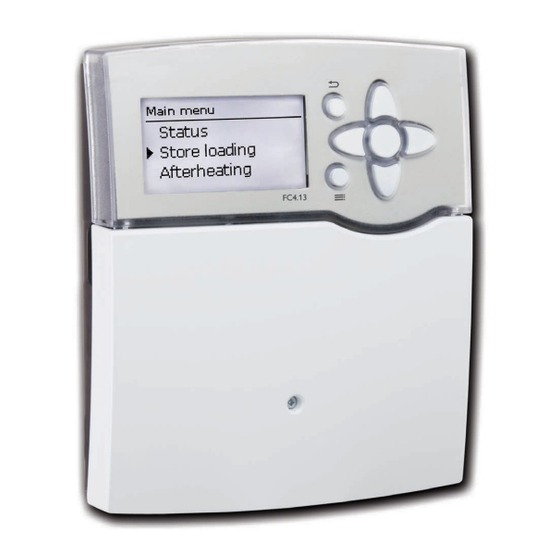
Operation and function 2.3.1 Buttons 2.3.2 Selecting menu points and adjusting values The controller is operated via the 7 buttons next to the display. They have the During normal operation of the controller, the display is in the main menu. If no following functions: button is pressed for a few seconds, the display illumination goes out. - Page 11 Values and adjustments can be changed in different ways: adjusted value (not yet confi rmed) adjustment channel If only one item of several can be selected, they will be indicated with "radio but- tons". When one item has been selected, the radio button in front of it is fi lled. If button ➄...
- Page 12 Adjusting the timer When the Timer option is activated, a timer is in- Î The end of a time frame can be determined by dicated in which time frames for the function can be pressing button ➄. adjusted. Î In order to add another time frame, repeat the First of all, an overview of the current adjustments is last three steps.
- Page 13 2.3.3 Menu structure Main menu Status Status Store loading Store loading Meas. / Balance values Afterheating Afterheating Emergency operation Store loading Circulation Circulation AH sensor T-HW set Afterheating ∆T on Strat. return Type Set min Circulation ∆T off Disinfection Basic settings Circ.
-
Page 14: Commissioning Menu
Commissioning menu When the controller is commissioned or when it is reset, it will run a commis- sioning menu after the initialisation phase. The commissioning menu leads the user through the most important adjustment channels needed for operating the system. The commissioning menu consists of the following channels which can be entered and adjusted line by line. -
Page 15: Heat Transfer Controller Adjustments
Heat transfer controller adjustments Main menu 8. Completing the commissioning menu: Î In order to save the adjustments, select Save. The controller is then ready for operation and normally the factory settings will give close to optimum operation. Î In order to get back to the commissioning menu channels, press button ➆. - Page 16 3.2.1 Meas. / Balance values In the Status / Meas. / Balance values menu, all current measurement values as In the Meas. /Balance values / Store loading menu, information about the heat well as a range of balance values are displayed. Some of the menu items can be quantity generated in the secondary circuit is indicated, e.
- Page 17 3.2.4 Circulation 3.2.7 Parallel relay In the Status / Parallel relay menu, the status of the parallel relay (active or In the Status / Circulation menu, the status of the circulation, the circulation type inactive) is indicated. selected and, if applicable, remaining runtimes and blocking times are indicated. 3.2.8 Messages 3.2.5 Disinfection In the Status / Messages menu, error and warning messages are indicated.
-
Page 18: Store Loading
Store loading The Emergency operation function can be used for ensuring the hot water supply and loading of the secondary store in the case of a sensor fault. In this case the pumps will run at the adjustable Em. prim. and Em. sec. For this purpose, the emergency speed must be aligned with the resulting temperature at the hot water fl ow sensor in the secondary circuit. - Page 19 Maximum speed of the primary pump Maximum speed of the secondary pump Main menu / Store loading / Prim. max. speed Main menu / Store loading / Sec. max. speed Adjustment range / Factory Adjustment range / Factory Adjustment channel Description Adjustment channel Description selection setting...
- Page 20 ∆T store Maximum hot water set temperature Main menu / Store loading / ∆T store Main menu / Store loading / Set max Adjustment Adjustment range / Factory Adjustment range / Factory Description Adjustment channel Description channel selection setting selection setting Set difference between hot water set tempera- Set max...
-
Page 21: Circulation
Blocking protection Permanent afterheating If the system SUS Sys2 or Sys3 and the AH mode Source have been selected, the afterheating will heat the primary store up to the temperature (T-HW set + ∆T off), as soon as the temperature at sensor S3 falls below (T-HW set + ∆T on). Demand-dependent afterheating If the system SUS Sys2 or Sys3 and the AH mode Source and sink have been select- ed, the afterheating will heat the primary store up to the temperature (T-HW set +... - Page 22 The Timer function works as follows on the different circulation types: Main menu / Circulation Adjustment Adjustment range / Factory Circulation type Active inside time frames Active outside time frames Description channel selection setting Thermal Thermal No circulation Off, Demand, Thermal, Type Circulation type Continuous operation Continuous operation...
- Page 23 Temp. Sensor 3.4.2 Manual offset of the circulation pump 3.4.3 Disinfection 9 10 11 12 13 14 15 16 PWM2 PWM3 PWM4 +VBus- 0-10V 0-10V 0-10V 30 31 32 Main menu / Disinfection Main menu / Circulation / Circ. fl . rate Adjustment Adjustment range / Factory...
-
Page 24: Stratified Return
Scald danger! WARNING! Scalding may occur if T-disinf. set is adjusted to a value higher than 60 °C. PWM3 PWM1 Circulation Note: While the thermal disinfection is active, a suffi cient temperature in the primary store and heat supply by the boiler must be ensured. PWM2 Î... -
Page 25: Basic Settings
Note: SD card If the Difference mode is adjusted, the controller uses the S5 sensor input for measuring the store sensor temperature. The 3-port valve has to be mounted such that it is normally open towards the lower store zone or the cooler store respectively. In order to protect the stratifi ca- tion in the upper store zone or the warmer store respectively, the store sensor must be mounted in the upper store zone or the warmer store respectively. -
Page 26: Manual Mode
Stopping the logging Manual mode Î Select the menu item Remove card… Î After Remove card is displayed, remove the card from the slot. When Linear is adjusted in the Logging type adjustment channel, data logging will stop if the capacity limit is reached. The message Card full will be displayed. If Cyclic is adjusted, the oldest data logged onto the SD card will be overwritten as soon as the capacity limit is reached. -
Page 27: User Code
Manual mode 3.10 Inputs Adjustment Adjustment range / Factory Description channel selection setting All relays… Operating mode of all relays Auto, Off Auto Controller Operating mode of the primary pump On, Auto, Off Auto Operating mode of the secondary pump On, Auto, Off Auto Operating mode of the circulation pump... -
Page 28: Heat Transfer Controller Data Communication
Heat transfer controller data communication Data communication / Bus The controller is equipped with a VBus for data transfer with and energy supply ® to external modules. The connection is carried out at the two terminals marked VBus and GND (either polarity). One or more VBus modules can be connected ®... -
Page 29: Troubleshooting
Troubleshooting Electric shock! WARNING! Upon opening the housing, live parts are exposed! If a malfunction occurs, a message will appear on the display of the controller. Î Always disconnect the controller from power supply before opening the housing! The controller is protected by a fuse. The fuse holder (which also holds the spare fuse) becomes accessible when the cover is removed. - Page 30 Notes Pump noise can be heard, bubbling in the pipes. DHW heating does not work Controller in operation? System vented? Check the controller; Check the fuse of and the power supply to the Vent the system. controller. System vented? Draw-off amount is too small. Vent the system.
- Page 31 Message on Cause Related function Required for re-commissioning Standalone Cascade the display controller controller !Sensor fault Temperature sensor fault - Function using this sensor After repair, the function will automatically be reactivated and the error message deleted. !T-FL T-ST_FL sensor fault - Sliding set temperature After repair, the function will automatically be reactivated and the error message deleted.
- Page 32 Message on Cause Related function Required for re-commissioning Standalone Cascade the display controller controller Blocking pro- Blocking protection activated and current- Î Deactivate blocking protection. tection active ly active for pumps and valves Desinf. Disinfection function completed success- successful the fully, disinfection temperature for required [##.##.##] disinfection duration reached...
-
Page 33: Index
Index Balance values ......................... 16 Offset ............................27 Operating hours counter ..................... 16 Blocking protection ....................... 21 Operating mode, relays ......................26 Circulation ..........................21 Circulation pump offset ......................23 Parallel relay ..........................27 Circulation sensor ......................... 22 Commissioning menu ......................14 Relay / sensor allocation ...................... - Page 36 PAW GmbH & Co. KG Distributed by: Böcklerstraße 11 31789 Hameln Tel.: +49 (0) 51 51 / 98 56 - 0 Fax: +49 (0) 51 51 / 98 56 - 98 www.paw.eu info@paw.eu © All contents of this document are protected by copyright.
Need help?
Do you have a question about the FC4.13 and is the answer not in the manual?
Questions and answers