PAW FC3.10 Installation And Operation Instruction Manual
For dhw modules
Hide thumbs
Also See for FC3.10:
- Installation and operation instructions manual (40 pages) ,
- Assembly, installation and operation instructions (80 pages) ,
- Installation and operation instruction manual (88 pages)
Table of Contents
Advertisement
Quick Links
Advertisement
Table of Contents

Related Manuals for PAW FC3.10


Summary of Contents for PAW FC3.10
- Page 1 PAW GmbH & Co. KG Böcklerstr. 11, 31789 Hameln - Germany Phone: +49-5151-9856-0, Fax: +49-5151-9856-98 E-mail: info@paw.eu, Web: www.paw.eu Installation and Operation Instructions Controller FC3.10 for DHW modules 2021/03 99E13331xx-mub-en - V07...
- Page 2 Translation of the original instructions PAW GmbH & Co.KG We reserve the right to make technical changes without notice! Böcklerstraße 11 Printed in Germany – Copyright by PAW GmbH & Co. KG 31789 Hameln - Germany 99E13331xx-mub-en - V07 2021/03...
-
Page 3: Table Of Contents
1 General Information Contents General Information ......................7 Scope of these instructions ..................7 Designated use ......................7 Target group ........................ 7 Safety instructions ......................8 Mounting and installation [specialist] ................9 Installation of the controller................... 9 Establishing the electrical connections ............... 11 Product description and operation .................. - Page 4 1 General Information Messages ........................22 Service ........................22 Controller ........................22 Hot water ........................23 Functions ........................23 10 General settings ......................24 10.1 Language ........................24 10.2 Date ........................... 24 10.3 Time ........................... 24 10.4 Synchronise date/time ....................25 10.5 Auto daylight saving time ...................
- Page 5 1 General Information 14 User code ........................30 15 Advanced settings ......................30 15.1 Min speed* ......................... 30 16 Description of function ....................31 16.1 Circulation ........................31 16.2 Stratification (stratification of return) ................35 16.3 Modulating hot water temperature ................36 16.4 Comfort function ......................
- Page 6 1 General Information 20.1 Status ......................... 52 20.2 General settings ......................53 20.3 USB ........................... 53 20.4 Automatic / manual mode ................... 53 20.5 Advanced settings* ....................53 21 Functions in the cascade network .................. 53 21.1 Circulation ........................54 21.2 Stratification of return ....................
-
Page 7: General Information
, is an independently installed electronic temperature controller for on-surface installation. The maintenance-free controller is exclusively intended for the controlling and monitoring of a PAW domestic hot water module. Improper usage of the controller excludes any liability claims. Only use PAW accessories with the controller. -
Page 8: Safety Instructions
2 Safety instructions 2 Safety instructions The installation and commissioning as well as the connection of electrical components require technical knowledge commensurate with a recognised vocational qualification as a fitter for plumbing, heating and air conditioning technology, or a profession requiring a comparable level of knowledge [specialist]. -
Page 9: Mounting And Installation [Specialist]
3 Mounting and installation [specialist] 3 Mounting and installation [specialist] Installation of the controller NOTICE The following section describes only the installation of the controller. Follow the instructions of each respective manufacturer when installing external components (valves etc.) Do not put the controller into operation in case of any visible damage. 1. - Page 10 3 Mounting and installation [specialist] Inputs FriwaMini: Terminal Individual operation mode / Cascade operation mode S1, Ʇ Flow temperature, primary (T-VL) S2, Ʇ Optional: Storage tank temperature (T-SP), ext. circulation temperature, ext. stratification temperature S3, Ʇ Optional: Storage tank temperature (T-SP), ext. circulation temperature, ext.
-
Page 11: Establishing The Electrical Connections
3 Mounting and installation [specialist] Establishing the electrical connections WARNING Risk to life and limb due to electric shock! Make sure that the following conditions are met when performing the work described in this section: All cables leading to the controller must be disconnected from the power ... - Page 12 3 Mounting and installation [specialist] NOTICE Any connection polarity may be used for the 1 – 4 signal inputs and outputs. Only type Pt1000 temperature sensors may be used. Lay the sensor cables at least 100 mm away from any power supply cables. ...
-
Page 13: Product Description And Operation
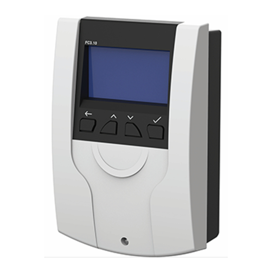
4 Product description and operation 4 Product description and operation View of the controller Display with hydraulic scheme Operating buttons USB service interface (below the front panel) Operating buttons / key combination Description Button Back: goes back to the next higher level or back to the system overview Upwards: navigates upwards in the menu, increases adjustment values... -
Page 14: Display
4 Product description and operation Display Remaining time of Flow rate (VFS V) Flow temperature disinfection (T-VL) Hot water Time with day of temperature the week (T-DHW) Speed of the primary Speed of the pump (PWM 1) Cold water circulation pump temperature (T-CW) (PWM 2) Symbols... -
Page 15: Commissioning [Specialist]
5 Commissioning [specialist] 5 Commissioning [specialist] DANGER Risk to life and limb due to electric shock! Mounting and Be sure to perform all the measures listed in the installation section before starting the first commissioning. When the controller is connected for the first time, the message "Please carry out the first start- up"... -
Page 16: Time
5 Commissioning [specialist] Time Sets the current time. S E T T I M E First set the hours, then the minutes. 09 : 16 H o u r Automatic daylight saving time / standard time Activates/deactivates the automatic daylight saving time / standard time. When the controller is delivered, this item is activated. -
Page 17: Finish With Protocol
5 Commissioning [specialist] Finish with protocol Saves the commissioning with creating a protocol. For this, an external memory (USB flash drive) must be connected to the service interface / USB port. This interface can only be accessed after removal of the front panel, see chapter 4.1. 5.10 Finish without protocol Completes the commissioning without a further saving on an external USB flash drive. -
Page 18: Menu Settings
6 Menu settings By pressing the operating button ( ), the menu of the controller FC3.10 opens. The menu bar contains multiple submenus in which you can find or modify various settings. The available menu items of the first three levels are shown as a menu tree and will be explained in detail in the following chapters. -
Page 19: Status
6 Menu settings Measured values Messages Status Service Controller D.H.W. set temperature Hot water D.H.W. set temperature min* D.H.W. set temperature max* Circulation Stratification of return Modulating hot water temperature Comfort function Disinfection Functions Alarm relay Parallel relay Hygienic flush/protection against blocking Buffer storage* Reheating*... -
Page 20: Usb
6 Menu settings Registration DHCP IP address Internet module Netmask Gateway DNS address Information Eject memory Load settings Save settings Save alarms history Save parameters history Data logging interval Recording type Format drive Properties Automatic mode Sensor simulation Relay 1 Auto / Manual mode Relay 2 User code... -
Page 21: Status
7 Status 7 Status status The menu item contains submenus which allow to S T A T U S look through all measured/balance values, temperatures M e a s u r e d / b a l a n c e v a l u e s and flow rates at the sensors, relay states, operating R e p o r t s times, heat quantity, tap performance as well as error... -
Page 22: Messages
7 Status Messages This menu item displays the occurring errors which the controller diagnosed. If an error occurs, the displays shows a symbol ( ); and A L A R M an error message with information about the error is shown. -
Page 23: Hot Water
8 Hot water 8 Hot water In this menu item, you can make the temperature D . H . W . S E T T E M P E R A T U R E settings for the hot water preparation. 60 °C 6 0 °... -
Page 24: General Settings
10 General settings In the example, the ticked check box indicates that the F U N C T I O N S Circulation function is active at the moment. C i r c u l a t i o n S t r a t i f i c a t i o n o f r e t u r n M o d u l a t i n g h o t w a t e r t e m p e r a t u r e C o m f o r t f u n c t i o n... -
Page 25: Synchronise Date/Time
10 General settings 10.4 Synchronise date/time Activates/deactivates the synchronisation of date and time. The synchronisation is only possible in connection with an internet module. 10.5 Auto daylight saving time Activates/deactivates the automatic daylight saving time / standard time When the controller is delivered, this item is activated. 10.6 Commissioning* Opens the commissioning menu to go through the settings again. -
Page 26: Internet Module
Synchronisation of the time with the Internet Additional instructions are enclosed to the WiFi-/Ethernet module. The following data can be additionally set in the domestic hot water controller FC3.10: 11.1 Registration The registration is required to retrieve data of the domestic hot water module via the Internet and to make settings. -
Page 27: Usb
12 USB 12 USB The controller has a service interface (USB port) for standard USB flash drives. To connect a USB flash drive, first remove the EPP insulation around the controller. In a second step, unscrew the screw in the lower area of the controller and remove the white front panel. The USB port is at the right of the display at the side of the controller. -
Page 28: Data Logging Interval
12 USB 12.6 Data logging interval Setting the data logging interval for the data recording. The log interval defines how regularly data should be recorded on the external storage medium. 12.7 Recording type Selecting of the type of the data recorded. A L A R M M E S S A G E Linear If in the menu item "Recording type"... -
Page 29: Auto / Manual Mode
13 Auto / manual mode Properties Properties of the USB flash drive 13 Auto / manual mode In this menu item, you can set the operation mode of all used PWM outputs and relays in the controller as well as a sensor simulation. With the sensor simulation, a certain temperature can be set for a sensor in order to simulate this temperature. -
Page 30: User Code
14 User code Relay 1 Relay 1 Automatic, manual Automatic mode (on, off) Relay 2 Relay 2 Automatic, manual Automatic mode (on, off) Relay 3 Relay 3 Automatic, manual Automatic mode (on, off) PWM 1 PWM control of the Automatic / manual Automatic primary pump mode (0.0 ... -
Page 31: Description Of Function
16 Description of function 16 Description of function 16.1 Circulation By means of a circulation function, the drinking water in the circulation line is heated to the desired nominal temperature. The designated circulation pump is actuated by the controller via the PWM 2 connection. During the first commissioning of the circulation pump, you should specify the following parameters to adapt the operation of the domestic hot water module to the current circulation line:... - Page 32 16 Description of function NOTICE An additional external circulation sensor can be defined. This can be useful to minimise the runtimes of the circulation pump or to determine the temperatures of pipes with a bad circulation. The circulation function offers 3 operating modes which can be combined with each other. Temperature control •...
- Page 33 16 Description of function Operation mode "on demand mode" Is a tap open for a few seconds (max 5 s) and closed, the flow rate sensor detects this tap on demand mode impulse. If the is activated, this tap impulse initiates the switch-on of the circulation pump for the determined runtime.
- Page 34 16 Description of function Meaning Adjustment range Factory setting Parameters Circulation active Activates the On, Off function Temperature control Submenu for On, Off settings of the temperature control Switch-on temperature Sets the switch-on 35 ... 75 °C 55 °C temperature ΔT off ΔT for the 2 ...
-
Page 35: Stratification (Stratification Of Return)
16 Description of function 16.2 Stratification (stratification of return) This function serves to improve the temperature stratification in the storage tank or to avoid a temperature mix. In the return can be considerable temperature differences (for example, with an existing circulation). Therefore, the return is connected to the storage tank via a three-way valve. -
Page 36: Modulating Hot Water Temperature
16 Description of function NOTICE If the three-way valve was not activated in the last 24 hours, it is opened and closed automatically. This prevents that the valve seizes up after a longer downtime. Parameters Meaning Adjustment range Factory setting Stratification of return Activates the function On, Off... -
Page 37: Comfort Function
16 Description of function 16.4 Comfort function The comfort function controls the operation of the primary pump when there is no withdrawal and circulation. To speed up the start-up process of the module, the flow to the heat exchanger can be warmed up and be maintained on a certain temperature. -
Page 38: Disinfection
16 Description of function 16.5 Disinfection WARNING Danger of scalding due to hot water! If the function is activated, there is the risk of scalding during the defined time window at all withdrawal points! Inform user Make sure to avoid scalding at the installation ... -
Page 39: Alarm Relay
16 Description of function Parameters Meaning Adjustment range Factory setting Disinfection Activates the function On, Off Manual disinfection Manual start of the On, Off disinfection Disinfection temperature Sets the disinfection 60 ... 80 °C 60 °C temperature Disinfection duration Sets the duration of the 10 ... -
Page 40: Parallel Relay
16 Description of function measuring range at the flow rate sensor μC error μC error On, Off Time error Time not defined or lost On, Off Comm error Communication error in the On, Off cascade network Disinfection error Disinfection not successfully On, Off completed 16.7 Parallel relay... -
Page 41: Hygienic Flush/Protection Against Blocking
16 Description of function Disinfection Connects in parallel to the On, Off disinfection Disinfection error Connects in parallel if On, Off disinfection was not successful 16.8 Hygienic flush/protection against blocking Hygienic flush/protection against blocking The function serves to avoid that the circulation pump seizes up after a longer downtime. -
Page 42: Reheating
17 Installation of the cascade controller 16.10 Reheating* If the temperature in the buffer tank is not sufficiently high, a reheat request can be sent to the boiler via a defined relay. If the buffer tank temperature is equal or less than the hot water nominal temperature + 3 K, the relay is switched on. -
Page 43: Installation
17 Installation of the cascade controller In the following illustration you can see an example of a 4-fold cascade. To connect the two-way zone valves (cascade valves), the three-way valve for the improved stratification control in the storage tank (return stratification) as well as the controller via a bus line, follow the steps in chapter 17.1. - Page 44 17 Installation of the cascade controller 1. Remove the white front panel of the controller. 2. Remove the strain reliefs. 3. Remove the sensor cables of the VFS/US sensors, of the PWM signal and the temperature sensors from the controller circuit board plug connector. 4.
- Page 45 17 Installation of the cascade controller Cascade valve (at the left) 3-way valve (at the right) Brown - L (via duo wire end ferrule) Brown - L (via duo wire end ferrule) Black – L (R1) White – L (R2) Blue –...
- Page 46 17 Installation of the cascade controller Pos. 1 Pos. 2 1. For the first and last participant of the modbus communication, the jumpers must be placed in position 2 (see upper illustration). Place the jumpers as follows: Number of Client Server 1 Server 2 Server 3...
-
Page 47: Initial Commissioning Of The Cascade Controller
17 Installation of the cascade controller 17.2 Initial commissioning of the cascade controller If the entire cascade is hydraulically filled and electrically connected, the mains connection must be established. In the case of an initial commissioning and the first mains connection of the cascade controllers, Commissioning start the installation in the menu item C O N T R O L L E R T Y P E... -
Page 48: Extension Of A Single Controller To A Cascade Network
17.3 Extension of a single controller to a cascade network If you already have a FC3.10 domestic hot water system as a single controller and if you wish to extend it to a cascade network, you first need to enter the installation code. For more information, see chapter 14. -
Page 49: Menu Settings Cascade
18 Menu settings cascade By pressing the operating button ( ), the menu of the controller FC3.10 opens. The menu bar contains multiple submenus in which you can find or modify various settings. The available menu items of the first three levels are shown as a menu tree on the basis of the client and will be explained in detail in the following chapters. -
Page 50: Submenu Cascade At The Client
19 Submenu Cascade at the client Cascade 19 Submenu at the client Cascade The main setting options were already described in the chapters 7-16. The submenu is only visible at the client and contains the following setting parameters: 19.1 Cascade switchover points If a withdrawal flow rate falls under or over the determined threshold, an additional domestic hot water module is switched off or on via the cascade valve. -
Page 51: Switchover Delay
19 Submenu Cascade at the client 19.4 Switchover delay* Allows to set a delay after which time a new module is meant to switch on/switch off. For example, if the threshold for the switching on of a module is exceeded, the next module is only switched on after the defined switching delay. -
Page 52: Submenus At The Server
20 Submenus at the server Parameters Meaning Adjustment Factory setting range Cascade switchover Overview for the points minimum flow rate when a module is activated or switched off. Switchover point ON Threshold for the 70 ... 100 % 80 % minimum flow rate when the next module is activated... - Page 53 21 Functions in the cascade network 20.2 General settings In the general settings, you can make modifications at the servers via the display. These include brightness Dim brightness luminosity ( ), dimmed luminosity ( ) and contrast. It is also possible to make a software update. 20.3 USB If a USB flash drive is connected to the controllers, you must make the corresponding settings Eject memory...
- Page 54 21 Functions in the cascade network 21.1 Circulation NOTICE The settings for the circulation menu can only be made and monitored via the client in the cascade network. In addition, the circulation pump must be electrically connected via the client. For further information, see chapter 17.1.
- Page 55 21 Functions in the cascade network 21.2 Stratification of return NOTICE The settings for the stratification can only be made and monitored via the client in the cascade network. The three-way valve and the external sensor, which is meant to be used for the function, must be electrically connected to the controller of server 1.
-
Page 56: Buffer Tank
21 Functions in the cascade network When a disinfection starts, all cascade valves are opened. This means, all modules carry out the disinfection at the same time. The disinfection is logged as "successful" when, during the duration of the disinfection, the temperature at the cold water inlet (with circulation) or hot water outlet (without circulation) has Disinfection OK exceeded the temperature (disinfection temperature - 5 K) for the defined time... -
Page 57: Technical Data
22 Technical data 22 Technical data General Rated voltage (system voltage) 115...230 V/AC, 50/60 Hz Own consumption < 2.5 W Own consumption standby < 1 W Max. power consumption inclusive outputs < 4.2 A Outputs Outputs R1, R2 Type Relay Switching current 1 (1) A Voltage... -
Page 58: Error Correction
23 Error correction Signal outputs Number Frequency 200 Hz Voltage 10 V Current (max.) 10 mA Modbus Number of connections RJ10 Type Internal bus Number of connections RJ12 Type Application conditions Protection type IP 20, DIN 40050 [without front panel: IP 20] Protection class Ambient temperature 0...50 °C, in the case of free wall assembly... - Page 59 23 Error correction NOTICE The controller is a quality product which was conceived for numerous years of continuous operation. Please observe the following aspects: The cause of an error is often not the controller but one of the connected components. The following notes about fault localisation indicate the most frequent causes of error.
-
Page 60: Troubleshooting
23 Error correction 23.2 Troubleshooting Pump noises can be heard, bubble noises in the pipe. System vented? Vent the system! Withdrawal quantity is too low. Is the water pressure in the secondary circuit of the system sufficient? Does the plate heat exchanger Check the pressure in the has limescale build-up? secondary circuit of the system;... - Page 61 23 Error correction The withdrawal temperature is too low. Is the DHW nominal temperature at the controller set sufficiently high? Is the pressure loss in the primary Increase the setting circuit of the system too high? value for the DHW nominal temperature at the controller.
- Page 62 23 Error correction The display is permanently blank. Confirm + Back Press button at the same time. Display lighting switched on? Check the power supply of Controller was in standby, the controller. everything is ok! Is it interrupted? Check the cause and A technical fault could have establish the power occurred, please...
-
Page 63: Checking The Vfs 2-40 Flow Sensor
23 Error correction 23.3 Checking the VFS 2-40 flow sensor WARNING Risk of death by electrocution! Disconnect the device from the power supply before opening the body. All work on the open device may only be carried out by professional ... -
Page 64: Checking The Flowsonic Flow Sensor
23 Error correction Signal configuration VFS 2-40 Designation Technical description Cable Temperature signal 0.5-3.5 V measured to pin 3 Yellow Flow signal 0.5-3.5 V measured to pin 3 White Ground Green Power supply 5 V/DC Brown Pin-assignment flow signal Pin assignment temperature signal 23.4 Checking the FlowSonic flow sensor WARNING Risk of death by electrocution! - Page 65 23 Error correction Assignment tension - flow Voltage 0.350 0.38 0.50 0.66 0.82 0.97 1.13 1.29 1.45 1.60 1.76 Flow Standby [l/min] Voltage 1.924 2.081 2.239 2.396 2.554 2.711 2.869 3.026 3.184 3.341 3.499 Flow [l/min] Signal configuration FlowSonic Designation Technical description Cable Temperature signal...
-
Page 66: Disposal
24 Disposal 24 Disposal NOTICE Electrical and electronic devices must not be disposed of in the household waste. For your return, there are free collection points for electrical appliances and, if necessary, additional points of acceptance for the reuse of the devices in your area. -
Page 67: Legal Guarantee
26 Legal guarantee 26 Legal guarantee In accordance with German statutory regulations, there is a 2-year legal guarantee on this product for the customer. The seller will remove all manufacturing and material faults that occur in the product during the guarantee period and affect the correct functioning of the product. Natural wear and tear does not constitute a malfunction. - Page 68 PAW GmbH & Co.KG www.paw.eu Böcklerstraße 11 Phone: +49 5151 9856 - 0 Fax: +49 5151 9856 - 98 31789 Hameln - Germany 99E13331xx-mub-en - V07 2021/03...
Need help?
Do you have a question about the FC3.10 and is the answer not in the manual?
Questions and answers