PAW FC3.10 Installation And Operation Instructions Manual
Dhw modules
Hide thumbs
Also See for FC3.10:
- Installation and operation instruction manual (68 pages) ,
- Assembly, installation and operation instructions (80 pages) ,
- Installation and operation instruction manual (88 pages)
Table of Contents
Advertisement
Quick Links
Advertisement
Table of Contents

Related Manuals for PAW FC3.10


Summary of Contents for PAW FC3.10
- Page 1 PAW GmbH & Co.KG Böcklerstr. 11, D-31789 Hameln Phone: +49 (0)5151-9856-0, Fax: +49 (0)5151-9856-98 E-mail: info@paw.eu, Web: www.paw.eu Installation and Operation Instructions Controller FC3.10 for DHW modules 2019/09 99E13331xx-mub-en - V02...
- Page 2 Translation of the original instructions PAW GmbH & Co.KG We reserve the right to make technical changes without notice! Böcklerstraße 11 Printed in Germany – Copyright by PAW GmbH & Co. KG D - 31789 Hameln, Germany 99E13331xx-mub-en - V02 2019/09...
-
Page 3: Table Of Contents
1 General Information Contents Contents ..........................3 General Information ......................5 Scope of these instructions ..................5 Designated use ......................5 EC Declaration of Conformity ..................5 Target group ........................ 5 Safety instructions ......................6 Assembly and installation [specialist] ................7 Assembly of the controller .................... - Page 4 1 General Information Basic settings ......................26 6.7.1 Language ......................26 6.7.2 Automatic DST ....................26 6.7.3 Date ........................26 6.7.4 Time ........................27 6.7.5 Display ........................ 27 6.7.6 Updating the firmware ..................27 6.7.7 Information ......................27 USB ........................... 27 Manual operation .......................
-
Page 5: General Information
The integration into a pump assembly is possible when the technical specifications of the controller are adhered to. The maintenance-free controller is exclusively intended for the controlling and monitoring of a PAW domestic hot water module. Only use PAW accessories with the controller. -
Page 6: Safety Instructions
2 Safety instructions 2 Safety instructions The installation and commissioning as well as the connection of electrical components require technical knowledge commensurate with a recognised vocational qualification as a fitter for plumbing, heating and air conditioning technology, or a profession requiring a comparable level of knowledge [specialist]. -
Page 7: Assembly And Installation [Specialist]
3 Assembly and installation [specialist] 3 Assembly and installation [specialist] Assembly of the controller NOTICE The following section describes only the installation of the controller. Follow the instructions of each respective manufacturer when installing external components (valves etc.). 1. Temperature sensors 2. - Page 8 3 Assembly and installation [specialist] Input: Terminal Individual operation mode / Cascade operation mode S1, Ʇ Flow temperature, primary (T-FL) S2, Ʇ Domestic hot water temperature, secondary T) S3, Ʇ Optional: Sensor for storage tank temperature (T-SP) S4, Ʇ Cold water temperature, secondary (T-CW) VFS/US1 VSF-/Ultrasonic sensor Outputs:...
-
Page 9: Establishing The Electrical Connections
3 Assembly and installation [specialist] Establishing the electrical connections WARNING Risk to life and limb due to electric shock! Make sure that the following conditions are satisfied when performing the work described in this section: All cables leading to the controller must be disconnected from the power ... - Page 10 3 Assembly and installation [specialist] NOTICE Any connection polarity may be used for the 1 – 4 signal inputs and outputs. Only type Pt1000 temperature sensors may be used. Lay the sensor cables at least 100 mm away from any power supply cables. Use shielded sensor cables when inductive sources are present, e.g.
-
Page 11: Commissioning [Specialist]
4 Commissioning [specialist] 4 Commissioning [specialist] DANGER Risk to life and limb due to electric shock! Be sure to perform all the measures listed in the Installation section before starting the first commissioning. If the controller is connected for the first time, the message "Please carry out the first start-up" is displayed on the screen. -
Page 12: Product Description
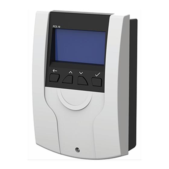
5 Product description 5 Product description Screen Heat exchanger Storage tank Button - Button - Confirm Back Navigation keys Symbol Description Pump Three-way valve with flow direction Water withdrawal point Temperature sensor Flow sensor Current operation mode 99E13331xx-mub-en - V02 2019/09... -
Page 13: Operation
6 Operation 6 Operation Block diagram 2019/09 99E13331xx-mub-en - V02... -
Page 14: Status
6 Operation Status The menu item makes it possible to look through all the active functions, temperatures at the sensors, relay states, operating times of the devices and alarm history/messages. Hot water (HW) 6.3.1 Domestic hot water nominal temperature This menu item makes it possible to regulate the domestic hot water temperature to the value that has been set. -
Page 15: Dynamic Domestic Hot Water Control
6 Operation The nominal temperature for the comfort function (T-Comf.ON) can not be set freely, but is calculated dynamically. T-Comf.ON, min = 1 K T-Comf.ON, max = 10 K T-Comf.ON = dynamic = T-HW-Soll - T-Comf.ON Default setting = 7 K Due to the comfort nominal temperature (T-FL, S1) depending on the current hot water temperature (T-HW-Soll, VFS) a conflict in the function "Dynamic T-HW control"... -
Page 16: Blocking Protection
6 Operation 6.3.4 Blocking protection Upon activation of this function, the controller checks for the time of the last activity of the actuators (stratification, switch valve, pumps). If no actuator had been active in the last 24 hours, all of them are actuated one after another for the parameter "Blocking protection". Default setting = off Functions NOTICE... - Page 17 6 Operation Example: It is possible to balance the circulation again anytime. NOTICE During the cascade operation mode, the circulation pump is connected to the master. During the adjusting process, only the station of the master controller is connected (cascade valve master = on). The cascade valves of the slaves are closed.
- Page 18 6 Operation Operating mode circulation: Temperature controlled The T-CW sensor (cold water sensor) is defined as the temperature sensor for the temperature controlled circulation function. If the temperature measured at the cold water sensor is smaller than the switch-on threshold, the circulation pump is switched on. If the temperature measured at the cold water sensor greater than the switch-off threshold, the circulation pump is switched off.
- Page 19 6 Operation Operating mode circulation: Time controlled If the controller detects a withdrawal (in cascade operating mode: overall tapping) with a duration of less than 5 s (tap impulse), the circulation pump is switched on for the set duration. After the switch-on duration has elapsed, the circulation pump is switched off for the time of the delay.
-
Page 20: Stratification
6 Operation NOTICE The following modes can be combined: Time control + temperature control: The temperature control is only active during a certain time window. Demand + Temperature control: The circulation is switched on on demand. The circulation is switched off when the switch-off temperature is exceeded or the operation time has elapsed. - Page 21 6 Operation The return is fed into the upper or the lower part of the storage tank, depending on the position of the valve. There are two modes for this function: Thermostat mode: Using the T-CW sensor in the station. •...
-
Page 22: Thermal Disinfection
6 Operation NOTICE When the mode "temperature difference" is activated, the controller uses the sensor input "S3" to determine the storage tank temperature. The three-way valve has to be installed in such a way that in a currentless state the flow direction is switched towards the colder part of the storage tank. - Page 23 6 Operation The thermal disinfection can be switched-on with a weekly timer or started manually. Unlike the weekly timer, the thermal disinfection can only be set for one time window per day. The length of the time window is adjustable. For safety reasons the thermal disinfection is automatically deactivated after one hour runtime when it was started manually.
-
Page 24: Alarm Relay
6 Operation Definition of the message "Thermal disinfection completed successfully": The temperature of the return is higher than the parameterised disinfection temperature for a certain time. Example: T-CW > 60 °C; 10 min As soon as the temperature falls below the threshold, the time span is displayed in minutes. If the disinfection does not complete successfully within the time window, a corresponding "nlO"-message is saved. -
Page 25: Parallel Relay
6 Operation - Function "thermal disinfection" not completed successfully (nIO)(activatable) The alarm output remains switched on as long as the controller display shows the error message. The alarm output can be selected as a "normally open contact" or a "break contact". The function can be activated or deactivated (default setting = OFF, because a relay must be selected). -
Page 26: Back-Up Heating
6 Operation The function also makes it possible to display the temperature of the buffer tank. Any free sensor input can be selected as a sensor. If the storage tank temperature is equal or less than the cold water temperature, the •... -
Page 27: Time
6 Operation 6.7.4 Time ᴧ ᴠ The keys are used to set the current time of day. Afterwards, the settings need to be confirmed using the ✔ key. 6.7.5 Display The function makes it possible to adjust the display to the individual needs. The user can adjust parameters like display luminosity, contrast as well as inversion of the colours and is able to switch off the screen lock. -
Page 28: Manual Operation
6 Operation Manual operation In the menu manual mode, the operating mode of all PWM outlets and relays used can be set in the controller. Operating modes: Manual • 0 – 100 % PWM1 0 – 100 % PWM2 on/off (relays) Auto •... -
Page 29: Technical Data
7 Technical data 7 Technical data Inputs / Outputs Rated voltage (system voltage) 115...230 V ~, 50/60 Hz Own consumption < 2.5 W Own consumption Standby < 1 W Outputs R1, R2 Number Type Relays Switching current 1 A each Voltage 115…230 V~, 50/60 Hz Output R3... - Page 30 7 Technical data Display Type LCD with background lighting Application conditions Protection type IP 20, DIN 40050 [without front panel: IP 20] Protection class Ambient temperature 0...+ 50 °C, in the case of free wall assembly Physical values Dimensions L x W x H 164 x 112 x 55 mm Weight 390 g...
-
Page 31: Error Messages / Error Correction
8 Error messages / Error correction 8 Error messages / Error correction General error correction DANGER Risk of death by electrocution! Immediately disconnect the device from the power supply if it can no longer be operated safely, f. ex. in the case of visible damage. Disconnect the device from the power supply before opening the housing. - Page 32 8 Error messages / Error correction Alarm Possible cause Problem solution Sensor 1 damaged - check sensor for - short circuit or failure Sensor 2 damaged proper connection of the sensor Sensor 3 damaged - damaged sensor Sensor 4 damaged Error VFS DV Error VFS T No PWM signal of the base...
-
Page 33: Checking Flow Sensor Vfs 2-40
8 Error messages / Error correction Checking flow sensor VFS 2-40 DANGER Risk of death by electrocution! Disconnect the device from the power supply before opening the housing. All work on the open device may only be carried out by professional ... -
Page 34: Checking Flow Sensor Flowsonic
8 Error messages / Error correction Signal configuration VFS 2-40 • Designation Technical description Cable Temperature signal 0.5-3.5 V measured to pin 3 Yellow Flow signal 0.5-3.5 V measured to pin 3 White Ground Green Power supply 5 V/DC Brown Pin assignment flow signal Pin assignment temperature signal Checking flow sensor FlowSonic... - Page 35 8 Error messages / Error correction Assignment tension - flow • Voltage [V] 0.35 0.380 0.506 0.664 0.821 0.979 1.136 1.294 1.451 1.609 1.766 Flow [l/min] 0 Standby Voltage [V] 1.924 2.081 2.239 2.396 2.554 2.711 2.869 3.026 3.184 3.341 3.499 Flow [l/min] Signal configuration FlowSonic •...
-
Page 36: Exclusion Of Liability
9 Exclusion of liability 9 Exclusion of liability The manufacturer can neither monitor the compliance with this manual nor the conditions and methods during the installation, operation, usage and maintenance of the controller. Improper installation of the system may result in damage to property and, as a result, to bodily injury. -
Page 37: Legal Guarantee
10 Legal guarantee 10 Legal guarantee In accordance with German statutory regulations, there is a 2-year legal guarantee on this product for the customer. The seller will remove all manufacturing and material faults that occur in the product during the guarantee period and affect the correct functioning of the product. Natural wear and tear does not constitute a malfunction. - Page 38 10 Legal guarantee 99E13331xx-mub-en - V02 2019/09...
- Page 39 10 Legal guarantee 2019/09 99E13331xx-mub-en - V02...
- Page 40 PAW GmbH & Co.KG www.paw.eu Böcklerstraße 11 Phone: +49 (0) 5151 9856 - 0 D - 31789 Hameln, Germany Fax: +49 (0) 5151 9856 - 98 99E13331xx-mub-en - V02 2019/09...
Need help?
Do you have a question about the FC3.10 and is the answer not in the manual?
Questions and answers