Table of Contents
Advertisement
Quick Links
Advertisement
Table of Contents

Related Manuals for PAW Domestic


Summary of Contents for PAW Domestic
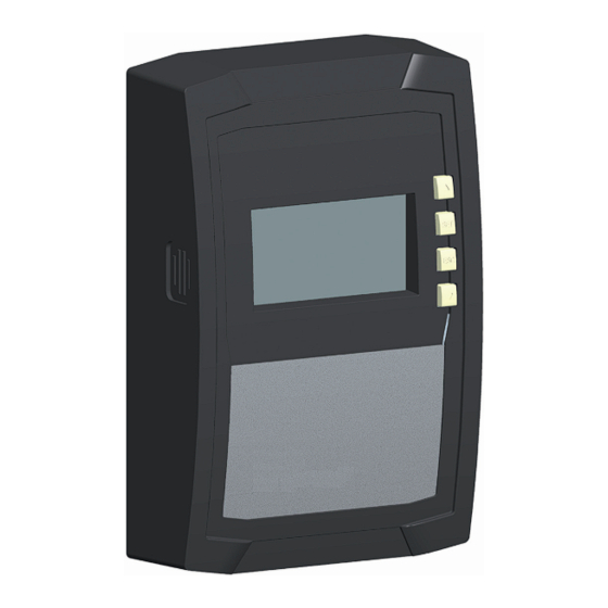
- Page 1 Domestic hot water controller FC3.8 6 (8) inputs, 4 outputs (3 relays, 1 potential-free switch output) Installation and Operation Instructions 99B138120x-mub-en | 2014/11 | V05 99B138120x-mub-en | V05 | 2014/11 | Subject to change due to technical improvements!
-
Page 2: Table Of Contents
............... 24 Setting the time ............24 Setting the functions ..........24 Set nominal temperature of the domestic hot water . 24 Switch on thermal disinfection ........25 Reset to factory settings ........... 25 Adjust hydraulic variant ..........26 Functions ..............26... -
Page 3: General Safety Instructions
Exception: End-customers may operate the device when they have previously been trained by a technical professional. • The domestic hot water module can be damaged by improper operation of the device. • The device must not be connected to the mains power supply when: –... -
Page 4: Proper Usage
The integration into a pump assembly is possible when the technical specifications of the controller are adhered to. The maintenance-free controller is exclusively intended for the controlling and monitoring of the domestic hot water module Friwa. Only use original accessories for the controller. About this manual Contents This manual contains all information required by a technical professional for setting up and operating the domestic hot water controller. -
Page 5: Installation
Installation Note The following section describes only the installation of the controller. Follow the instruc- tions of each respective manufacturer when installing external components (valves etc.) Opening/closing the casing 3.1.1 Removing the front panel X Grasp the front panel by the grooves at the sides and pull forwards (Fig. -
Page 6: Mounting The Casing
Mounting the casing The controller is firmly attached. Only observe this chapter in case of servicing (change of the controller). √ The mounting location must satisfy the prescribed conditions of use; more information on this is provided in the Technical data section. √ The mounting surface is vertical and allows good access for installation. Danger Risk of death by electrocution! •... -
Page 7: Establishing The Electrical Connections
Establishing the electrical connections Danger Risk of death by electrocution! Make sure that the following conditions are satisfied when performing the work described in this section: • All cables leading to the controller must be disconnected from the power supply and it must be ensured that they cannot be unintentionally reconnected during installation. •... - Page 8 Connection: PWM = brown, = blue 7x ground connection (common ground for sensor inputs and control outputs) Multi-pin connector, only for internal use, 2x input for PAW FlowSonic (white) Cable openings on the rear side of the casing ...
- Page 9 3.3.2 Preparing the cable openings The cables can be fed through openings in the rear wall of the casing or at the bottom of the casing. The openings are pre-punched and must be prepared as required before installation. Prepare the cable openings in the rear wall of the casing as follows: 1.
- Page 10 Remove the plastic links as follows: 1. Insert a screwdriver under the right plastic link between the casing and the spring clamp (Fig. 5). 2. Carefully push the screwdriver to the left . Lever the spring clamp to the right ...
-
Page 11: Terminal Pin Assignments
Individual operation mode / Terminal Cascade operation mode Flow temperature, primary (TVL) Optional: sensor for tank temperature (TSP) Cold water temperature, secondary (TKW) E.1, T Domestic hot water temperature, secondary E.1, V‘ Flow rate, secondary Outputs Terminal Individual operation mode Cascade operation mode... - Page 12 FriwaMidi / FriwaMaxi / FriwaMega Inputs Individual operation mode / Terminal Cascade operation mode Flow temperature, primary (TVL) Domestic hot water temperature, secondary (TWW) Optional: sensor for tank temperature (TSP) Cold water temperature, secondary (TKW) E.1, T (Domestic hot water temperature, secondary) E.1, V‘...
-
Page 13: Commissioning The Device For The First Time
Commissioning the device for the first time Danger Risk of death by electrocution! Be sure to perform all the measures listed in the Installation section before starting the first commissioning. Note • When power is removed for a longer period of time (> 15 min after a long period of power supply), the time and the date must be reset (following steps 1 –... -
Page 14: Design
Construction Casing No. Element section Operation mode button 6.1, 7 (under front panel) Operating buttons , SET, ESC, Display Front panel Terminal cover 3.3.1 Terminal cover fastening screw – Section 3.3.1 describes the terminals under the terminal cover. - Page 15 Flow rate sensor 3-way valve with flow direction 5.2.3 Settings menu The settings menu ( in fig 7) contains the following entries: Time Functions Nominal temperature of the domestic hot water Thermal disinfection Reset to factory defaults 5.2.4 Pictograms for functions The following table describes the pictograms used for functions ( in fig. 7). Symbol Description...
- Page 16 5.2.5 Operational and setting values The display of the operational and setting values ( in fig. 7) consists of the following elements: Symbol is displayed when an error occurs. Symbol for time control of functions. This symbol is displayed when: ...
-
Page 17: Operation
Operation This section contains general information on operating the controller. Operating buttons The device is operated using the buttons , , SET, ESC and as follows: • Scrolls up through the menu • Increases the setting value by 1 step •... -
Page 18: Off Mode
Variant display can be selected (see fig. below). Operation X Press SET in order to select the display of the preset variant of the domestic hot water module. X Press and at the same time and hold them for 2 seconds to display the variant selection. -
Page 19: Manual Mode
• Current temperatures and operating hours can be displayed (status display). • The display of the domestic hot water temperature shows an unequalized value. • When changing to manual mode all outputs are switched to A, R1 is displayed. •... - Page 20 You display the current temperatures and operating hours as follows: 1. Press ESC. The temperature/operating hours are displayed and the associated component flashes ( , display is not illustrated). 2. Press to select a different component. 3. Press SET to leave the temperature/operating hours display. 99B138120x-mub-en | 2014/11 | V05...
-
Page 21: Automatic Mode
Automatic mode Functioning The Automatic mode is preset when the device is delivered. Automatic is the normal operation mode and the system is automatically controlled. The following actions are possible: • Display status (status display): Display the status of external components (temperatures, switching states, run times) •... -
Page 22: Settings Menu
Settings menu Overview The following graphic provides an overview of the structure of the settings menu. Time Functions Domestic hot water Setting the Heat quantity - F:01 time Circulation - F:02 Diverting valve in the return - F:03 ... - Page 23 nominal temperature Thermal disinfection Factory settings 5 seconds Reset to factory settings 99B138120x-mub-en | 2014/11 | V05...
-
Page 24: Calling Up The Settings Menu And Selecting A Menu Entry
X Continue as described in the Functions section. Set nominal temperature of the domestic hot water Functioning The controller attempts to regulate the domestic hot water temperature to the value that has been set. The domestic hot water temperature can be changed within the following limits. -
Page 25: Switch On Thermal Disinfection
Switch on thermal disinfection Functioning If necessary, the domestic hot water module reaches higher domestic hot water temperatures in order to kill all dangerous germs. At the same time the circulation pump is actuated if the circulation function is activated. If no circulation function is active, the nominal temperature of the domestic hot water is increased in the defined time window to the disinfection temperature. -
Page 26: Adjust Hydraulic Variant
Adjust hydraulic variant The controller can represent all stations and is preset for the corresponding variant. In case of servicing the variant must be reset, if necessary. Operation mode Off is selected. √ 1. Press SET. 2. Press and at the same time for 2 seconds. 3. - Page 27 Activating the function A function must be activated (activation = on) and all the associated characteristics must be correctly set before it can be used. If a function is activated and then exited before the characteristics are set then oFF flashes briefly (fig. left). After this, the function is displayed with a switching state of oFF (function is deactivated).
-
Page 28: Function Descriptions
The function can only be activated or deactivated. Measured value display: The measured values are displayed in the status menu. The current output and the daily heat quantity are displayed after the domestic hot water values. Current thermal output: By pressing SET the respective max. value is displayed. - Page 29 9.2.2 Circulation Switches a circulation pump on and off on a temperature, time and/or tap controlled basis. These three types of control can be combined as required. In order to activate the circulation the speed setting of the pump has to be confirmed and one operation mode has to be activated. Temperature control: If the temperature in the circulation return falls below the T value, then the circulation pump is switched on until the T...
- Page 30 Speed control of the circulation pump The speed of the circulation pump has to be set during the first commissi- oning. After the activation of F02 (on) press the key . At regular intervals the speed (in %), the flow rate (in l/min) and the flow and return temperature (in °C) are displayed alternately. After pressing the SET key (speed value is displayed and flashes) the speed of the circulation pump has to be confir- med by the SET or set by the keys or . After the confirmation of the speed value you can control the setting by the help of the flow rate and the temperature. In order to guarantee a sufficient thermal disinfection, the temperature difference between inlet and outlet...
- Page 31 The measured values are displayed in the status menu. The temperature of the cold water sensor and the operating hours of the diverting valve are displayed after the domestic hot water values. Temperature of the cold water sensor: By pressing SET the respective min/max values are displayed.
- Page 32 The comfort nominal temperature can not be adjusted, it is automatically calculated on the basis of the current set nominal temperature of the domestic hot water (THW NOM - 7 K). In order to avoid a permanent operation of the primary pump because of a storage tank that is not hot enough, the controller carries out a security query. If within 100 s after the start of the comfort function the flow tempe-...
- Page 33 9.2.5 Bypass • only available for FriwaMaxi with bypass or FriwaMega with bypass Improves the control of the nominal temperature of the domestic hot water for small withdrawal quantities and high source temperatures. The primary flow rate and the flow temperature are lowered and the open bypass valve mixes cooled water from the return with the flow water. Depending on the measured tap quantity and the temperature difference between the measured source temperature and the current adjusted DHW temperature the bypass is activated or deactivated.
- Page 34 The temperature sensor is connected to terminal 3, and is optionally available. The temperature sensor has to be an immersion sensor that is placed at the buffer tank near the connection of the domestic hot water module. No further settings are necessary.
- Page 35 9.2.7 Modulating hot water temperature Adjusts the nominal temperature of the domestic hot water to the tempera- ture level of the buffer tank for preheating systems obtaining their energy from buffer tanks without back-up heating or for the improvement of the efficiency of systems with unstable temperatures (THW NOM = T - 5 K).
- Page 36 The deactivation of the second module when the flow rate falls below the lower limit of 60% (30% of the flow rate of each module). Condition: Performance indicator 1 (as per SPF test procedure) with a flow temperature of the storage tank of 60° C, a domestic hot water temperature of 45 °C and a cold water temperature of 10 °C. FriwaMini / LK1: 30 l/(min*Modul) Flow rate for the addition of the 2nd module: 24 l/min...
- Page 37 The following options are available: Display kind of communication bus: - no communication bus: 1 eBUS bus: 2 data string to the PAW Modbus Server (every 10 seconds) bus: 3 in case of servicing communication with the service software 99B138120x-mub-en | 2014/11 | V05...
-
Page 38: Alarm Output
European Waste Electronic and Electrical Equipment Directive. For further questions please contact the local authorities, responsible for the disposal. Information messages Display Description The bypass is active. flashes The modulating domestic hot water temperature is active. flashes The hygienic flushing is active, see section Circulation. flashes 99B138120x-mub-en | 2014/11 | V05... -
Page 39: Information Messages
Information messages Warning Risk of death by electrocution! • Immediately disconnect the device from the mains supply when it can no longer be operated safely, e.g. in the case of visible damage. • Disconnect the device from the mains power before opening the case. •... -
Page 40: General Faults
H1 is set to > 10% Automatic • is displayed Primary pump is running, domestic hot water is tapped, no heat transport in the heat ex- changer. Air in the primary circuit Check the primary circuit for air The isolating valve is closed. -
Page 41: Fault Messages
A short-circuit was detected at the Check the cable and sensor displayed sensor input connected to the sensor input. (in this case: sensor input 4). The nominal temperature of the domestic hot water can not be reached. Possible causes: • Storage tank is not heated •... -
Page 42: Fault At Sensor
Effect on regulation Flow temperature, primary (TVL) The controller assumes 75 °C as provisional value in order to continue operating the control. Domestic hot water temperature, Controller uses temperature value of the sensor secondary (TWW) E.1, T for the control. -
Page 43: Checking The Pt1000 Temperature Sensors
12.4 Checking the Pt1000 temperature sensors Warning Risk of death by electrocution! Before opening the device, make sure that all cables leading to the device have been disconnected from the mains power and cannot be unintentionally reconnected to the mains power. 1. -
Page 44: Checking The Vfs 2-40 Flow Sensor
12.5 Checking the VFS 2-40 flow sensor • only for FriwaMini Warning Risk of death by electrocution! Before opening the device, make sure that all cables lea- ding to the device have been disconnected from the mains power and cannot be unintenti- onally reconnected to the mains power. -
Page 45: Checking The Flowsonic Flow Sensor
12.6 Checking the FlowSonic flow sensor • only for FriwaMidi, FriwaMaxi, FriwaMega Warning Risk of death by electrocution! Before opening the device, make sure that all cables leading to the device have been disconnected from the mains power and cannot be unintentionally reconnected to the mains power. -
Page 46: Technical Data
Technical data Inputs/outputs Rated voltage (system voltage) 115 ... 230 V~, 50/60 Hz Own consumption ≤ 0.8 W, two Pt1000 temperature sensors connected Outputs R1, R2 Number Type triac Switching current 1.1 (1.1) A each Voltage 115 ... 230 V~, 50/60 Hz Output R3 Number Type relay Switching current 2.0 (2.0) A Voltage... -
Page 47: Cable Specifications
13.1 Cable specifications Mains cable Mains cable type H05 VV-... (NYM…) External diameter of mantle 6.5 mm to 10 mm Conductor cross-section Single strand (solid) ≤ 2.5 mm Fine strand (with core end sleeves) ≤ 1.5 mm Diameter of the internal strain relief 6.5 mm to 10 mm Signal cable Sensor cable length ≤ 100 m, including extension... - Page 48 PAW GmbH & Co. KG Böcklerstr. 11, D-31789 Hameln, Germany Phone: +49-5151-9856-0, Fax: +49-5151-9856-98 E-mail: info@paw.eu, Web: www.paw.eu 99B138120x-mub-en | 2014/11 | V05...
Need help?
Do you have a question about the Domestic and is the answer not in the manual?
Questions and answers