
Subscribe to Our Youtube Channel
Related Manuals for CTC Union SCD111 Series


Summary of Contents for CTC Union SCD111 Series
- Page 1 SCD111 Series Monitoring System SCD111 Series Monitoring System 4 Sensor Inputs 4 Sensor Inputs Product Manual Product Manual...
-
Page 2: Table Of Contents
Table of Contents • Introduction . . . . . . . . . . . . . . . . . . . . . . . . . . . . . . . . . . . . . . . . . . . . . . . . . . . . . . . . . . . . . . . . . . .3 •... -
Page 3: Introduction
. SCD111 The SCD111 Series system monitors a machine’s condition based on its level of vibration . The system can be integrated into a circuit to shut down a machine when preset vibration levels are reached . -
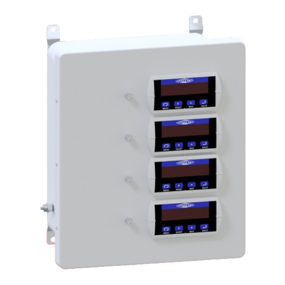
Page 4: Product Dimensions And Diagram
Product Dimensions NSIONS 13.82 in SHEET [351.2 mm] 7.43 in 11.90 in [302.2 mm] [188.7 mm] Front View Side View Figure 1. Dimensions Waveform Outputs Vibration Level Displays Figure 2. Diagram... -
Page 5: Mounting Instructions
Mounting Instructions Independent stainless steel mounting feet are included on the enclosure . Wall anchoring screws are not included . Note: If you have purchased a SCD111 series enclosure without cable entries provided, you should add your own entry prior to mounting the enclosure . -
Page 6: Conduit Entry
Conduit Entry If you are running conduit to your enclosure, ensure the conduit cable entry enters from the bottom of the enclosure when mounted . Note: To ensure moisture will not flow into the enclosure, a hole should be drilled at the lowest point in the conduit to provide drainage for any moisture . -
Page 7: Grounding
Grounding Ensure the shield ground wire on the SCD111 Series enclosure is grounded to earth ground . A. Mounting to Earth Ground When mounting SCD111 Series enclosures to earth ground (such as an I-Beam), mount the shield ground wire using a mounting bolt through one of the mounting brackets on the enclosure . - Page 8 B. Mounting to Non-Grounded Structure When mounting the SCD111 enclosure to a non-grounded structure, ensure the shield ground wire or customer-supplied ground wire is tied to a source of earth ground . Figure 6. Ground Wire Placement...
-
Page 9: Electrical Connections
Figure 7. Front View Wiring Inputs and Outputs When purchasing signal conditoners with an SCD111 Series enclosure, CTC will install and wire the signal conditioners inside the enclosure prior to shipment . If a signal conditioner requires a replacement post installation, use the following... - Page 10 Wiring Single Channel Vibration (Voltage) Wiring Inputs Wiring Outputs Signal Display Signal Display Conditioner Terminal Conditioner Terminal Terminal Block Block Cable Terminal Block Block Cable Position Position Color Destination Position Position Color Destination Black Power In (+) BNC (+) Dynamic Output (+) White Power In (-)
- Page 11 Wiring Single Channel Vibration (4-20 mA) Wiring Inputs Wiring Outputs Signal Display Signal Display Conditioner Terminal Conditioner Terminal Terminal Block Block Cable Terminal Block Block Cable Position Position Color Destination Position Position Color Destination Black Power In (+) BNC (+) Dynamic Output (+) White...
- Page 12 Wiring Single Channel Vibration (Voltage) with Temperature Wiring Inputs Wiring Outputs Signal Display Signal Display Conditioner Terminal Conditioner Terminal Terminal Block Block Cable Terminal Block Block Cable Position Position Color Destination Position Position Color Destination Black Power In (+) BNC (+) Dynamic Output (+) White...
- Page 13 Wiring Single Channel Vibration (4-20 mA) with Temperature Wiring Inputs Wiring Outputs Signal Display Signal Display Conditioner Terminal Conditioner Terminal Terminal Block Block Cable Terminal Block Block Cable Position Position Color Destination Position Position Color Destination Black Power In (+) BNC (+) Dynamic Output (+)
- Page 14 Wiring Power In order to supply power to the signal conditioners, the SCD111 features a power supply and circuit breaker . Below is the wiring configuration to bring live power into the enclosure . Note: Do not connect signal conditioners to live AC power. Cable Cable Color Ground...
-
Page 15: Configuring Relays
Configuring Relays The input to the internal controller comes from the vibration transmitter . They are built with a specific full-scale range and frequency band . The full-scale range of the transmitters must be known for the controllers to display the correct vibration value . - Page 16 level reaches 0 .65 IPS-pk . To reset the LOC relays, the vibration level must fall below the reset point of 0 .60, then press the ACK for relay two . Once the vibration level falls below 0 .30, press the ACK to reset relay 1 . Analog Output The analog 4-20mA signal represents the amount of vibration energy present at each channel based on the internal transmitter’s full scale, i .
-
Page 17: Troubleshooting
Troubleshooting If there is no sensor wired to the sensor input terminal, the corresponding transmitter for that channel will not power on . This will cause the Output Display to read low or negative values . Be sure to power the system on AFTER the sensor has been connected . - Page 18 Warranty & Refund Warranty All CTC products are backed by our unconditional lifetime warranty . If any CTC product should ever fail, we will repair or replace it at no charge . Refund All stock products can be returned for a 25% restocking fee if returned in new condition within 90 days of shipment .
Need help?
Do you have a question about the SCD111 Series and is the answer not in the manual?
Questions and answers