
Subscribe to Our Youtube Channel
Related Manuals for CTC Union 589342301


Summary of Contents for CTC Union 589342301
- Page 1 Installer manual CTC Condensation drain Condensation water pipe IHB EN 2024-1 631071...
-
Page 3: Table Of Contents
Table of Contents 1 General Different versions of CTC Condensation drain 2 Pipe connections General Drain indoors Stone caisson Gutter drainage 3 Electrical connection CombiAir Contact information CTC Condensation drain Table of Contents |... -
Page 4: General
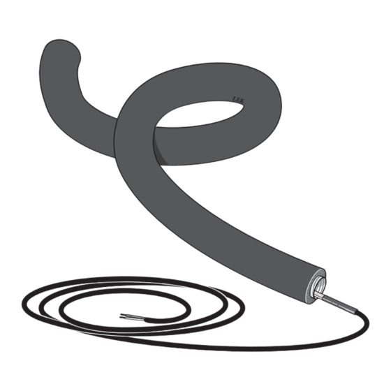
1 General The accessory CTC Condensation drain is used to safely divert most of the condensation from the air/water heat pump to a frost-free collection point. NOTE It is important to the heat pump function that condensation water is led away and that the drain for the condensation water run off is not positioned so that it can cause damage to the house. - Page 5 CTC Condensation drain 2x230V Part No. Part No. Hose length 1 metre (installation length 1 m without water seal) 589342301 589342304 Hose length 3 metres (installation length 1-2.2 m with water seal) 589342302 589342305 Hose length 6 metres (installation length 2.2-5.2 m with water...
-
Page 6: Pipe Connections
2 Pipe connections General Connect CTC Condensation drain to the heat pump's condensation water trough using the supplied hose clamp. ■ Pipe installation must be carried out in accordance with current norms and directives. ■ We recommend three ways of leading off condensa- tion water;... -
Page 7: Stone Caisson
Stone caisson Gutter drainage NOTE Bend the hose to create a water seal, see illus- tration. Frost proof Frostfritt djup depth Water seal Frost free Frostfritt If the house has a cellar the stone caisson must be posi- depth djup tioned so that condensation water does not affect the house. -
Page 8: Electrical Connection
3 Electrical connection Fuse NOTE Length, Fuse (F3) Part No. All electrical connections must be carried out heating by an authorised electrician. cable (m) CombiAir T100mA/250V 718 085 T250mA/250V 518 900* CTC Condensation drain connects to the communication T500mA/250V 718 086 board (AA23-X1:4-6) in CombiAir. - Page 9 CombiAir 6 Connection of residual current device RCD (FB1) between control board (PWB1) and communication board (AA23- X1:1-3). 230V 1/2 N AA23-X1 AA23-X1 2/1 N 230V 2AC 1/2 3/4 CTC Condensation drain Chapter 3 | Electrical connection...
- Page 10 CombiAir 8 Connection of residual current device RCD (FB1) between control board (PWB1) and communication board (AA23- X1:1-3). 230V/230V 2 AC 230V 1/2 N AA23-X1 AA23-X1 2/1 N 230V 2AC 1/2 3/4 Chapter 3 | Electrical connection CTC Condensation drain...
- Page 11 CombiAir 12, version 1 Connection of earth leakage circuit breaker (FB1) between terminal block (X1) and communication board (AA23- X1:1-3). 230V/230V 2 AC AA23-X1 AA23-X1 230V 230V 2AC 1/2 N 1/2 3/4 230V 2 A 2/1 N CTC Condensation drain Chapter 3 | Electrical connection...
- Page 12 CombiAir 12, version 2 Connection of residual current device RCD (FB1) between control board (PWB1) and communication board (AA23- X1:1-3). 230V/230V 2 AC AA23-X1 AA23-X1 230V 230V 2AC 1/2 N 1/2 3/4 230V 2 A 2/1 N Chapter 3 | Electrical connection CTC Condensation drain...
- Page 13 CombiAir 16 Connection of residual current device RCD (FB1) between control board (PWB1) and communication board (AA23- X1:1-3). 230V/230V 2 AC AA23-X1 AA23-X1 230V 230V 2AC 1/2 N 1/2 3/4 230V 2 A 2/1 N CTC Condensation drain Chapter 3 | Electrical connection...
- Page 14 Cable routing The following image shows recommended cable routing from distribution box to condensation water pipe. Route the heating cable (EB14) through the grommet under- neath and secure with two cable ties at the electrical connection. Transfer between electrical cable and heat- ing cable must occur after the lead-in to the condensa- 8.
- Page 15 12. Use cable ties and strap anchors to secure the heat- CombiAir 8, CombiAir 12, CombiAir 16 ing cable, see images. Strap anchors Secure the heating cable (EB14) here using two cable ties. 10. Stretch the heating cable and ensure that the marking on the heating cable is as close to the drain pipe as possible.
- Page 16 15. Install plugs, see image. CombiAir 6 CombiAir 8, CombiAir 12, CombiAir 16 Chapter 3 | Electrical connection CTC Condensation drain...
- Page 20 WS name: -Gemensamt WS version: a794 (working edition) Publish date: 2020-06-09 11:33 Enertech AB P.O Box 309 SE-341 26 Ljungby, Sweden www.ctc.se 631071...
Need help?
Do you have a question about the 589342301 and is the answer not in the manual?
Questions and answers