
Related Manuals for CTC Union PRO VPR100 Series


Summary of Contents for CTC Union PRO VPR100 Series
- Page 1 Product Manual MNX10023 / REV C MODEL VPR100 Series ViPR Multi Channel Monitoring System Delta-3N Kft. 7030 Paks, Jedlik Á. u. 2 Tel.: +36 75 510 115 Fax: +36 75 510 114 drnagyi@delta3n.hu www.delta3n.hu...
-
Page 2: Table Of Contents
Contents Section I Overview Introduction.................….… 2 Description..................2 ViPR Model Selection................. 2 Section II Installation Installation……………………………………………..…..……...… 3 Configuring Relays................4 Analog Output..................5 Section III Operation Operating Procedure................4 Section IV Maintenance General....................6 Warranty................... 10 Figures Figure 1 (VP Series Selection Guide)…..........2 Figure 2 (Cable Entry/Exit &... -
Page 3: Section I
User manuals are provided with the system for all configurable internal components. Description The PRO VPR100 Series system monitors a machine’s condition based on its level of vibration. The system can be integrated into a circuit to shutdown a machine when preset vibration levels are reached. The system detects high vibration energy being sensed by the input accelerometers and actuates relays based on alert and alarm set points. -
Page 4: Installation
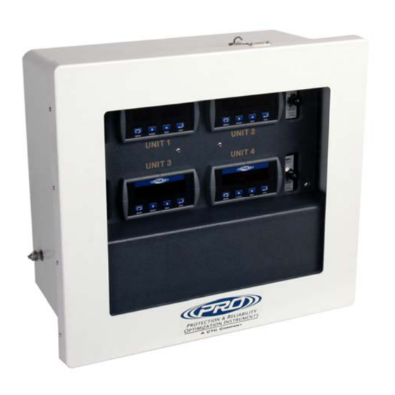
Section II Installation The VPR100 Series system is contained within a standard fiberglass junction box enclosure. Mounting brackets are provided for wall-mounting the enclosure. (Wall anchoring screws are not included). Cables enter and exit the enclosure through conduit fittings on the bottom of the unit. -
Page 5: Configuring Relays
Section III Operation Configuring Relays The input to the internal controller comes from the signal conditioners. They are built with a specific full scale range and frequency band. The Full scale range of the transmitters must be known in order for the controllers to display the correct vibration value. -
Page 6: Analog Output
Example Setup 1: A full scale range of 0 – 1 IPS has been specified. Baseline Vibration on the machine to be monitored is 0.18 IPS-pk. Alarm and Shutdown levels of vibration are specified as 0.35 IPS-pk and 0.65 IPS-pk respectively, reset points are specified as 0.30 IPS-pk and 0.60 IPS-pk. -
Page 7: Maintenance
Section IV Maintenance Once the system has been calibrated and installed it requires minimal maintenance. Basic checks to ensure system integrity should be made periodically. Visual Inspections should include examinations for the following: • The displays are operational • No visible electrical burns or smoke inside the enclosure •... -
Page 8: Figure 4 (Wiring Diagram)
2. This illustration shows the screw terminal panel suspended by the tether cables and the location of the wiring diagrams. Figure 4. Wiring Diagram After the Screw Terminal panel has been removed, the Main Panel needs to come out. Start by removing the (4) Phillips head screws holding the main panel. -
Page 9: Figure 6 (Signal Conditioners)
4. When the panel is dropped down and suspended by the tether cables, the SC200 series signal conditioners are now accessible. Figure 6. Signal Conditioners 5. Using a “Flat Blade” screwdriver, remove the lower connector block from the main unit. Figure 7. -
Page 10: Warranty
Figure 7. continued The block should have the Numbers 1-4on it. (shown right) For the Dynamic output, connect the wires to Terminals 3 & 4: • Terminal 3 – Positive output • Terminal 4 – Negative output Figure 8. Block Connections After wiring terminal blocks, re-insert them into the SC200 unit.
Need help?
Do you have a question about the PRO VPR100 Series and is the answer not in the manual?
Questions and answers