DAF LF45 Series Manual
Hide thumbs
Also See for LF45 Series:
- Service manual (254 pages) ,
- Manual (230 pages) ,
- Maintenance manual (128 pages)

Subscribe to Our Youtube Channel
Related Manuals for DAF LF45 Series


Summary of Contents for DAF LF45 Series
- Page 1 STRUCTURE ΛΦ45/55 series TECHNICAL DATA Structure SAFETY INSTRUCTIONS AND WARNINGS THREADED CONNECTIONS SEALS AND BEARINGS GENERAL OPERATIONS PAINT TREATMENT CONVERSION TABLES © 200338...
- Page 3 TECHNICAL DATA ΛΦ45/55 series Contents CONTENTS 0 Tech nical data Page Date VEHICLE MODELS ..........1-1 ..200338 Overview .
- Page 4 TECHNICAL DATA ΛΦ45/55 series Contents © 200338...
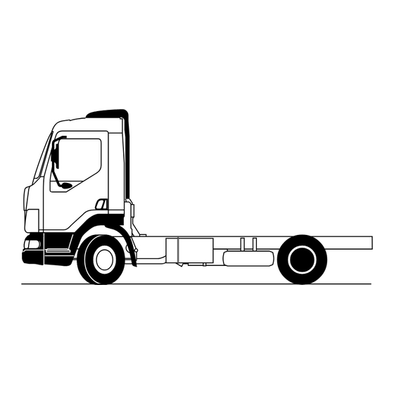
- Page 5 TECHNICAL DATA ΛΦ45/55 series Vehicle models 1. VEHICLE MODELS 1.1 OVERVIEW 4 x 2 6 x 2 steered axle driven axle G0 00 205 © 200338...
- Page 6 TECHNICAL DATA ΛΦ45/55 series Vehicle models © 200338...
- Page 7 TECHNICAL DATA ΛΦ45/55 series Locking compounds and sealants 2. LOCKING COMPOUNDS AND SEALANTS 2.1 GENERAL Certain cleaning agents have a negative effect on the functioning of locking compounds. The general rule is therefore that fasteners and components which have been cleaned with a cleaning agent must be treated with a cleaning liquid to ensure that the locking compound...
- Page 8 TECHNICAL DATA ΛΦ45/55 series Locking compounds and sealants Applying the locking compound Clean both the internal and external threads. Degrease the thread with a suitable degreasing agent which leaves no residue that could affect proper functioning. Apply one or more drops of locking compound to the thread, depending on the diameter.
- Page 9 TECHNICAL DATA ΛΦ45/55 series Locking compounds and sealants OVERVIEW OF SEALING COMPOUNDS Product Properties Applications name number Loctite Surface sealant, specially Sealing of aluminium parts 1441339 5205 designed for sealing aluminium parts Resistant to temperatures up to 150″C Resistant to water, coolant and oil Loctite Hardens on contact with metal For locking, fastening and sealing...
- Page 10 TECHNICAL DATA ΛΦ45/55 series Locking compounds and sealants OTHER PRODUCTS Product Properties Applications name number Syntheso Grease (green) Rubber guides for disc brake 1448908 GL EP1 Gleitmo Protects untreated metals For parts which are attached with a fit 1443160 against corrosion such as wheel hub units ©...
- Page 11 M2 00 001 Clamping flange bolt/standard-flange bolt Tightening torques for dipped threaded connections Overview of standard tightening torques for DAF flange bolts and nuts, strength class 10.9/10 Thread pitch Tightening torque (Nm) Extra angular displacement (≥ 10 %) for bolt stem length L (mm): L40...
- Page 12 395 ≥ 30 540 ≥ 40 680 ≥ 50 1000 ≥ 70 1350 ≥ 100 Overview of standard tightening torques for DAF flange bolts and nuts, strength class 12.9/12 Thread Tightening torque in Nm 32 ≥ 3 67 ≥ 5 113 ≥...
- Page 13 TECHNICAL DATA ΛΦ45/55 series Threaded connections Overview of standard tightening torques for DAF clamping flange bolts and nuts, strength class 12.9/12 Thread Tightening torque in Nm 178 ≥ 14 274 ≥ 22 425 ≥ 35 550 ≥ 45 Overview of tightening torques, banjo bolts...
- Page 14 TECHNICAL DATA ΛΦ45/55 series Threaded connections New bolts/nuts New DAF bolts and DAF nuts, except bolts M4 to M8 with inner-Torx, have already been lubricated. If bolts have not yet been lubricated, a lubricant should be applied. Apply one drop of engine oil to the first turn...
- Page 15 TECHNICAL DATA ΛΦ45/55 series Paint treatment 4. PAINT TREATMENT 4.1 OVERVIEW OF PLASTICS USED SMC polyester Thermoplastic polymer parts (ASA or ABS) Fibre-glass reinforced polyester 2 2 1 G0 00 206 © 200338...
- Page 16 TECHNICAL DATA ΛΦ45/55 series Paint treatment © 200338...
- Page 17 SAFETY INSTRUCTIONS AND WARNINGS LF45/55 series Contents CONTENTS Page Date SAFETY INSTRUCTIONS AND WARNINGS .......
- Page 18 SAFETY INSTRUCTIONS AND WARNINGS LF45/55 series Contents 0201...
- Page 19 SAFETY INSTRUCTIONS AND WARNINGS LF45/55 series Safety instructions and warnings 1. SAFETY INSTRUCTIONS AND WARNINGS 1.1 GENERAL SAFETY INSTRUCTIONS Warning symbol When text is accompanied by the warning symbol shown here, this indicates that the information provided is essential for the health and personal safety of the mechanic.
- Page 20 SAFETY INSTRUCTIONS AND WARNINGS LF45/55 series Safety instructions and warnings Remain at a safe distance from rotating and/or moving components. Do not remove the filler cap from the cooling system when the engine is at operating temperature. Be careful when changing the oil. Hot oil can cause serious injuries.
- Page 21 SAFETY INSTRUCTIONS AND WARNINGS LF45/55 series Safety instructions and warnings Always use the appropriate lifting gear (gearbox jack) or approved hoists for the removal and installation of heavy components. Attach the component securely to the lifting or hoisting gear. Be careful when working on systems which may be under pressure, such as a trailing axle lifting device, cab tilting mechanism, brake system, steering gear, fuel system,...
- Page 22 SAFETY INSTRUCTIONS AND WARNINGS LF45/55 series Safety instructions and warnings 1.2 BATTERIES Always charge batteries in a properly ventilated area and avoid sparking and naked flames. Always switch the battery charger off before removing the leads. Fast-charging should only be resorted to in an emergency.
- Page 23 LF45/55 series Safety instructions and warnings 1.3 WELDING No welding of the chassis is allowed without special, written permission by DAF. Exceptions to the above are the welding operations described in the manual “Superstructure directives”. Non-compliance with welding regulations may cause serious damage to the chassis.
- Page 24 SAFETY INSTRUCTIONS AND WARNINGS LF45/55 series Safety instructions and warnings Welding on the chassis When welding on the chassis, disconnect the connectors of all electronic equipment (including sensors and actuators), if they are within a 1-metre radius from the point being welded or within a 1-metre radius from the earthing point.
- Page 25 SAFETY INSTRUCTIONS AND WARNINGS LF45/55 series Safety instructions and warnings Position of feed-through connectors, earth and power supply cable The feed-through connectors (1), and supply cable (2) are located behind the front panel in the plastic case. G0 00 203 The earth cable (3) is located behind the front panel below the service brake valve.
- Page 26 SAFETY INSTRUCTIONS AND WARNINGS LF45/55 series Safety instructions and warnings 1.4 JUMP-STARTING - Never start the vehicle by means of a fast-charging device. - The engine may be started with the aid of jump leads using the power from separate auxiliary batteries (approx.
- Page 27 Always use special pliers (special tool, DAF no. 0694829) to fit nipples and banjo unions in polyamide pipes. Clamp the plastic pipe in the special pliers (1).
- Page 28 SAFETY INSTRUCTIONS AND WARNINGS LF45/55 series Safety instructions and warnings In the event of a leakage from a pipe coupling, unlimited tightening of the union nut or banjo bolt is not permitted. First check whether the leak is at the connection point between the pipe and coupling or at the connection point between coupling and the component housing.
- Page 29 SAFETY INSTRUCTIONS AND WARNINGS LF45/55 series Safety instructions and warnings When pipes are fitted so close together or so close to other parts of the vehicle that they may touch, they should be secured to prevent chafing. Use the specially developed pipe clamps. These pipe clamps are available for pipes with a diameter of 6, 10 and 22 mm.
- Page 30 SAFETY INSTRUCTIONS AND WARNINGS LF45/55 series Safety instructions and warnings 1.6 WIRING HARNESSES After the first wiring harness has been disconnected or replaced, it must be reconnected in the original manner and fastened. Protect the wiring harness against contact with sharp edges.
- Page 31 SAFETY INSTRUCTIONS AND WARNINGS LF45/55 series Safety instructions and warnings 1.7 AVOIDING THE RISK OF FIRE Check fuel pipes for leakage and fix any leakage immediately (see also Plastic pipes). When fitting steel fuel pipes take into account the points listed below. Fit the fuel pipe free from tension.
- Page 32 SAFETY INSTRUCTIONS AND WARNINGS LF45/55 series Safety instructions and warnings Always remember to re-fit the heat shields after removal. Never replace a defective fuse with a fuse of a higher rating. Never connect accessories which are not protected by a fuse. Check wiring which is not fuse-protected (battery leads, etc.), to make sure that it is undamaged and properly attached and...
- Page 33 80 cm. Only accessories approved by DAF for vehicles with an airbag and/or seat belt tensioner may be installed, in the place indicated by DAF and in the manner outlined by DAF. G0 00 235 0201 1-15...
- Page 34 The use of such equipment or objects in the vicinity of parts of the airbag/seat belt tensioner system is therefore not recommended. Only operations described in the DAF workshop manual and systems manuals are permitted on pyrotechnic systems (systems with airbag(s) and/or seat belt tensioner(s)).
- Page 35 The surface may only be cleaned using a dry cloth, a cloth dampened with water, or a cloth with a cleaner approved by DAF for this purpose. It is not allowed to scrap a vehicle if it still has non-activated airbags and seat belt tensioners on board.
- Page 36 SAFETY INSTRUCTIONS AND WARNINGS LF45/55 series Safety instructions and warnings 0201 1-18...
- Page 37 THREADED CONNECTIONS LF45/55 series Contents CONTENTS Page Date GENERAL .............
- Page 38 THREADED CONNECTIONS LF45/55 series Contents 0201...
- Page 39 THREADED CONNECTIONS LF45/55 series General 1. GENERAL 1.1 DIPPED THREADED CONNECTIONS DAF vehicles are fitted with threaded connections which have been treated with a lubricant (dipped threaded connection). Factory-galvanised bolts and nuts are wax-dipped. Black annealed and phosphatised bolts and nuts are oil-dipped. The advantage of...
- Page 40 Dry threaded connections are not permitted because of their highly variable friction coefficients. The following threaded connections are used on DAF vehicles: Fastenings with strength classes 8.8 and 8, flange bolts and nuts with strength classes 10.9 and 10, flange bolts and nuts with strength classes 12.9 and 12,...
- Page 41 THREADED CONNECTIONS LF45/55 series General Other threaded connections Threaded connections 8.8/8, 12.9/12 and clamping flange bolts 12.9/12 are tightened as standard only with a torque. For the standard tightening torques, see “Technical data”. If any of these threaded connections has to be tightened differently, this is indicated in the technical data for the component concerned.
- Page 42 THREADED CONNECTIONS General LF45/55 series 0201...
- Page 43 SEALS AND BEARINGS LF45/55 series Contents CONTENTS Page Date GASKETS .............
- Page 44 SEALS AND BEARINGS LF45/55 series Contents 0201...
- Page 45 SEALS AND BEARINGS LF45/55 series Gaskets 1. GASKETS 1.1 PAPER AND KLINGERIT GASKETS (rubber-aramide fibre) The workshop manual specifies when a gasket is required and it also gives information about the type of gasket to be used. Remove the old gasket before fitting a new one.
- Page 46 SEALS AND BEARINGS LF45/55 series Gaskets 1.2 LIQUID GASKETS The workshop manual specifies when a gasket is required and it also gives information about the type of gasket to be used. Liquid gaskets, which replace conventional gaskets, have been developed to seal flat connections.
- Page 47 Removing the seal If possible, remove the sealing ring with the special tool (DAF no. 1329458 or DAF nos. 0694928 (A) and 0484899 (B)). When removing the seal, take care not to damage the recess. M200971 A8 00 360...
- Page 48 SEALS AND BEARINGS LF45/55 series Seals Installing the seal Check the recess in which the seal is to be fitted for damage. Make good any damage. Look for any marks on the outside of the seal indicating the direction of rotation of the shaft.
- Page 49 SEALS AND BEARINGS LF45/55 series Bearings 3. BEARINGS 3.1 BEARINGS, GENERAL Bearings must be replaced if they are worn, in the case of pitting (small dents in the running surface) and/or if the bearings have been exposed to excess heat (blue spots). When fitting a bearing, make sure that no force is transmitted via the balls or rollers of the bearing.
- Page 50 SEALS AND BEARINGS Bearings LF45/55 series 3.2 FITTING BEARINGS INTO A BEARING HOUSING Fitting bearings into a bearing housing Always use the correct size of driving tool. Centre the driving tool accurately on the outer bearing race. Preferably press the bearing evenly into the housing, using a pressing tool.
- Page 51 GENERAL OPERATIONS LF45/55 series Contents CONTENTS Page Date PRESERVATION AND DE-WAXING ........
- Page 52 GENERAL OPERATIONS LF45/55 series Contents 0201...
- Page 53 GENERAL OPERATIONS LF45/55 series Preservation and de-waxing 1. PRESERVATION AND DE-WAXING 1.1 PRESERVATION Note: Observe the applicable environmental requirements. Clean the vehicle thoroughly so that all dirt and dust are removed. Use pressurised air to remove any residues from the vehicle. Cover all glazing, headlights and tail lights.
- Page 54 GENERAL OPERATIONS LF45/55 series Preservation and de-waxing 1.2 DE-WAXING Note: Observe the applicable environmental and safety requirements. The vehicle should preferably be placed on a grid floor. Most de-waxing agents are inflammable. The de-waxing area should be suitable for the safe use of such products.
- Page 55 GENERAL OPERATIONS LF45/55 series Cleaning vehicles 2. CLEANING VEHICLES 2.1 HIGH-PRESSURE CLEANER It is advisable to clean the vehicle with a high-pressure cleaner before starting maintenance or service operations. A clean environment makes the engineer’s work easier, and enables any vehicle defects to be noticed at an early stage.
- Page 56 GENERAL OPERATIONS Cleaning vehicles LF45/55 series Make sure that no water can enter the differential or the gearbox via the breathers. Make sure that no water can enter via the reservoir bleed screws of clutch, brakes, trailing axle, etc. The engine and engine compartment can be cleaned with a high-pressure cleaner.
-
Page 57: Table Of Contents
PAINT TREATMENT LF45/55 series Contents CONTENTS Page Date PAINT TREATMENT ........... . - Page 58 PAINT TREATMENT Contents LF45/55 series 0201...
-
Page 59: Paint Treatment
1. PAINT TREATMENT 1.1 GENERAL INSTRUCTIONS In the chapter “Paint treatment”, directives are provided for respraying and repairing DAF paint systems applied on various subsurfaces. The products to be used are supplied by a range of manufacturers. However, only use products from well-known manufacturers who can provide all products for the complete paint structure. - Page 60 Colour coding The DAF code number of the cab paint is on the paint identification plate. The paint identification plate is mounted on one of the vehicle’s door pillars. The DAF code number for the cab paint is also marked on the vehicle identity card.
- Page 61 PAINT TREATMENT LF45/55 series Paint treatment 1.2 RESPRAYING/PAINT REPAIRING OF CAB TOP COAT AND SMC POLYESTER PARTS Respraying of cab top coat and SMC polyester parts Remove any preserving agents, if applicable; see “General Operations”. Remove any rust with a rust-removal agent. Clean the area to be resprayed with a solvent.
- Page 62 PAINT TREATMENT Paint treatment LF45/55 series Paint repairing of cab top coat and SMC polyester parts Remove any preserving agents, if applicable; see “General Operations”. Remove any rust with a rust-removal agent. Clean the area to be repaired with a solvent.
-
Page 63: Respraying/Paint Repairing Chassis Finishing
PAINT TREATMENT LF45/55 series Paint treatment 1.3 RESPRAYING/PAINT REPAIRING CHASSIS FINISHING Remove any preserving agents, if applicable; see “General Operations”. Remove any rust with a rust-removal agent. Clean the area to be treated with solvent. Sand the area to be treated with P80 sand paper. -
Page 64: Respraying Seed Top Coats
PAINT TREATMENT Paint treatment LF45/55 series 1.4 RESPRAYING SEED TOP COATS These instructions relate to parts in steel, SMC (Sheet Moulding Compound) plastic or glass-fibre reinforced polyester. Remove any preserving agents, if applicable; see “General Operations”. Remove any rust with a rust-removal agent. Clean the area to be resprayed with a solvent. -
Page 65: Respraying Thermoplastic Polymer Parts
PAINT TREATMENT LF45/55 series Paint treatment 1.5 RESPRAYING THERMOPLASTIC POLYMER PARTS Thermoplastic polymers include the following “elastic” plastics: ASA, ABS and PUR. Remove any preserving agents, if applicable; see “General Operations”. Clean the area to be resprayed with a solvent. Sand the area to be resprayed with P180 sand paper Fine-sand with 3M Scotch Brite ultra fine or... -
Page 66: Respraying Glass-Fibre Reinforced Polyester Parts
PAINT TREATMENT Paint treatment LF45/55 series 1.6 RESPRAYING GLASS-FIBRE REINFORCED POLYESTER PARTS These parts can be recognised by the visible fibre-glass structure on the rear of the part, and the gel coating on the front of the part. Remove any preserving agents, if applicable;... - Page 67 PAINT TREATMENT LF45/55 series Paint treatment 16. If necessary, fine-sand with 3M Scotch Brite ultra fine or an equivalent product. 17. Remove any dust from the area to be resprayed with a Tack-rag cloth. 18. Blow ionised air over the area to be resprayed, or clean the area with an anti-static liquid.
- Page 68 PAINT TREATMENT Paint treatment LF45/55 series 0201 1-10...
- Page 69 CONVERSION TABLES LF45/55 series Contents CONTENTS Page Date CONVERSION TABLES ..........
- Page 70 CONVERSION TABLES Contents LF45/55 series 0201...
- Page 71 CONVERSION TABLES LF45/55 series Conversion tables CONSUMPTION km/l 1/100 km miles/gallon (imp) miles/gallon (US) n x 2.2825 n x 2.352 282, 5 235, 2 n x 0.83 n x 0.354 282, 485 n x 0.425 n x 1.202 235, 294 SPECIFIC CONSUMPTION g/kW.h g/hp.h...
- Page 72 CONVERSION TABLES Conversion tables LF45/55 series LENGTH inches feet yards mile (stat.) 0.03937 0.003281 0.001094 0.001 0.000001 0.0000006214 25.4 0.08333 0.2777 0.0254 0.0000254 0.00001577 304.8 0.3333 0.3048 0.0003048 0.0001894 914.4 0.9144 0.0009144 0.0005682 1000 39.37 3.281 1.0936 0.001 0.0006214 1000000 39370 3281 1093.6...
- Page 73 CONVERSION TABLES LF45/55 series Conversion tables PRESSURE kg/cm lbs/sq inch (p.s.i.) 0.00001 0.0000101 0.000145 0.0000987 100000 1.0197162 14.500364 0.9868813 98066.5 0.980665 14.22 0.9678 6894.76 0.0689476 0.070307 0.068046 101322.3 1.013223 1.0332 14.70 133.32 0.0013332 0.0013595 0.01934 0.0013158 3386.23 0.0338623 0.03453 0.4912 0.3342 9797.82 0.0979782...
- Page 74 CONVERSION TABLES Conversion tables LF45/55 series 0201...
Need help?
Do you have a question about the LF45 Series and is the answer not in the manual?
Questions and answers