Table of Contents
Advertisement
Quick Links
Advertisement
Table of Contents

Related Manuals for DFI ICX610-C621A


Summary of Contents for DFI ICX610-C621A
- Page 1 ICX610-C621A ATX Industrial Motherboard User’s Manual A-583-M-2007...
- Page 2 1. The changes or modifications not expressly approved by the party responsible for com- pliance could void the user’s authority to operate the equipment. 2. Shielded interface cables must be used in order to comply with the emission limits. User's Manual | ICX610-C621A...
-
Page 3: Table Of Contents
Video Configuration .......................32 SATA Configuration .......................32 USB Configuration ......................34 USB Power Control ......................34 PCI Express Configuration ....................35 Debug Configuration .....................35 UEFI Device Manager ....................36 SIO NCT6112D .......................36 H2O IPMI Configuration ....................38 Console Redirection ......................41 SIO AST2500/AST2510 ....................42 User's Manual | ICX610-C621A... - Page 4 • To reduce the risk of electric shock, unplug the power cord before removing the sys- tem chassis cover for installation or servicing. After installation or servicing, cover the system chassis before plugging the power cord. User's Manual | ICX610-C621A...
- Page 5 • Storage device such as hard disk drive, CD-ROM, etc. • Power adaptor External system peripherals may also be required for navigation and display, including at least a keyboard, a mouse and a video display monitor. User's Manual | ICX610-C621A...
-
Page 6: Security
6 x SATA 3.0 (up to 6Gb/s) RAID 0/1/5/10 1 x LPC 1 x 16-bit DIO SMBus 1 x SMBus Watchdog Output & System Reset, Programmable via Software from 1 to 255 sec/Min Timer Interval Security Infineon TPM2.0 (opt., MOQ required) User's Manual | ICX610-C621A... - Page 7 This function allows you to use a USB keyboard or USB mouse to wake up a system from the S3 (STR - Suspend To RAM) state. The Real Time Clock (RTC) installed on the system board allows your system to automatically power-on on the set date and time. User's Manual | ICX610-C621A...
-
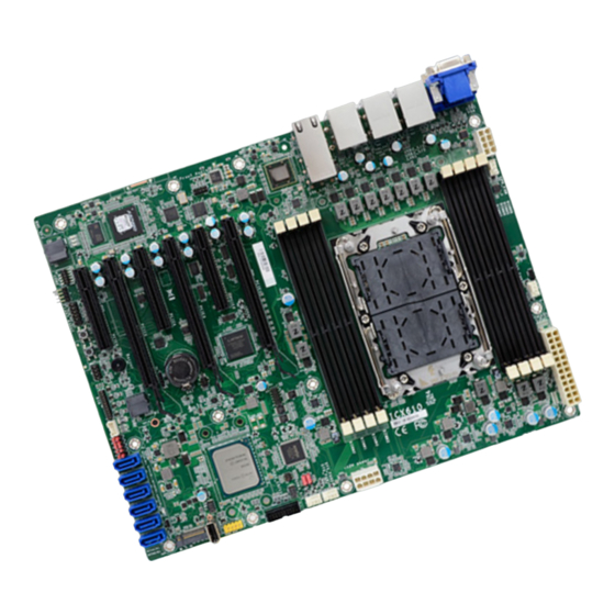
Page 8: Board Layout
PCIe 5 (PCIe x16) USB 2.0 BIOS M.2 M Key Buzzer PCIe 6 (PCIe x8) 2280 J8001 3 3 3 3 3 JP4/5/6/3/7 SATA 0 - 5 (left to right) COM2 Front Panel (left to right) User's Manual | ICX610-C621A... - Page 9 DIMMs in a channel can be identical or completely different. However, we highly rec- ommend using identical DIMMs. Not all slots need to be populated. Socket Side View Features • 8 288-pin ECC-RDIMM up to 512GB • Single Channel DDR4 up to 3200 MHz Step 1 Step 2 User's Manual | ICX610-C621A...
- Page 10 The tabs snap automatically to the edges of the card and lock the card in place. S ocket Side View Socket Side View Step 1 Step 1 Step 1 Step 1 Step 2 Step 2 Step 2 Step 2 Step 3 Step 3 Step 3 Step 3 User's Manual | ICX610-C621A...
- Page 11 CPU fan and heat sink assembly. If ® your CPU was purchased separately, make sure to only use Intel®-certified fan and heat sink. Latch Triangular mark Gold triangular mark Latch CPU Carrier (bottom view) User's Manual | ICX610-C621A...
- Page 12 (top view) Triangular hole 6. Connect the CPU fan’s CPU Fan power cable to the CPU fan connector on the system board. 4. Slide the protective caps open and detach them from the board. User's Manual | ICX610-C621A...
-
Page 13: Jumper Settings
1 and pin 2. 3. Plug the power cord and power-on the system. „ 1-2 On: Normal (default) „ 2-3 On: ME Force Update „ 1-2 On: Normal (default) „ 2-3 On: Clear RTC Registers User's Manual | ICX610-C621A... -
Page 14: Rear I/O Ports
The VGA port is used for connecting a VGA monitor. Connect the monitor’s 15-pin D-shell cable connector to the VGA port. After you plug the monitor’s cable connector into the VGA port, gen- tly tighten the cable screws to hold the connector in place. User's Manual | ICX610-C621A... -
Page 15: Com (Serial) Ports
2 x Intel I210AT PCIe (10/100/1000Mbps) ® • 1 x RTL8211F only with IPMI Note: The BMC COM port is used to monitor the IPMI, and may not be present when your model does not support IPMI. User's Manual | ICX610-C621A... -
Page 16: Usb Ports
USB ports, the +5V_standby power source of your power supply must support • 3 x USB 2.0 internal ports, one pin headers (USB 8/9) and one Type A (USB 7) ≥2A. • 2 x USB 2.0 rear ports (USB 10/11) User's Manual | ICX610-C621A... -
Page 17: Internal I/O Connectors
N.C. • 6 Serial ATA 3.0 ports with data transfer rate up to 6Gb/s Line2-R Mic2-JD • Integrated Advanced Host Controller Interface (AHCI) controller • Support RAID 0, RAID 1, RAID 5, RAID 10 Line2-L Line2-JD User's Manual | ICX610-C621A... -
Page 18: Cooling Fan Connectors
Insufficient power supplied to the system may result in instability or malfunction of the add-in boards and peripherals. Calculating the system’s approximate power usage is important to ensure that the power supply meets the system’s consump- tion requirements. User's Manual | ICX610-C621A... -
Page 19: Chassis Intrusion
Power On Suspend) state, it will blink at 1-second intervals. When the system is in the S3 (STR - Suspend To RAM) state, it will blink at 4-second intervals. Power Button This button is used to switch the system's power on or off . User's Manual | ICX610-C621A... -
Page 20: Expansion Slots
The M.2 socket is the Next Generation Form Factor (NGFF) which is designed to support mul- tiple modules and make the M.2 more suitable in application for solid-state storage. Note: The PCIe x16 slot will automatically switch to x8 bandwidth when the paired PCIe x8 slot is in use. User's Manual | ICX610-C621A... -
Page 21: Lpc
LAD1 the gap between the card and the stand-off closes up. The RST# LAD0 card should be lying parallel to the board when it’s correctly FRAME# VCC3 mounted. LAD3 LAD2 SERIRQ CLK_48M User's Manual | ICX610-C621A... -
Page 22: Battery
• There exists explosion hazard if the battery is incorrectly installed. • Replace only with the same or equivalent type recommended by the manufacturer. Assignment Assignment • Dispose of used batteries according to local ordinances. 3V3SB JTAG_PLD_TDO JTAG_PLD_TDI JTAG_PLD_EN_N JTAG_PLD_RST_N JTAG_PLD_TMS JTAG_PLD_TCK User's Manual | ICX610-C621A... -
Page 23: Dio
D_IOA1_C D_IOA9_C LVC3_SCL LVC3_SDA P U _ P C H _ T L S _ E N - D_IOA2_C D_IOA10_C N.C. ABLE_STRAP D_IOA3_C D_IOA11_C D_IOA4_C D_IOA12_C D_IOA5_C D_IOA13_C D_IOA6_C D_IOA14_C D_IOA7_C D_IOA15_C EMI_DIO_GND EMI_DIO_GND EMI_DIO_GND EMI_DIO_GND User's Manual | ICX610-C621A... -
Page 24: Dio Power
3 3 3 3 3 COM2 Front JP4/5/6/3/7 SATA 0 - 5 (left to right) Panel (left to right) The DIO Power is to provide power output for DIO. „ DIO Power Pin Assignment Assignment 5VSB User's Manual | ICX610-C621A... -
Page 25: Chapter 3 - Bios Settings
To display the submenu, move the highlight to disappears before you respond, restart the system or press the “Reset” button. You may also that field and press <Enter>. restart the system by pressing the <Ctrl> <Alt> and <Del> keys simultaneously. User's Manual | ICX610-C621A... -
Page 26: Main
The time format is <hour>, <minute>, <second>. The time is based on the 24-hour military-time clock. For example, 1 p.m. is 13:00:00. Hour displays hours from 00 to 23. Minute displays min- utes from 00 to 59. Second displays seconds from 00 to 59. User's Manual | ICX610-C621A... -
Page 27: Rc Acpi Configuration
“Wake On RTC” is enabled. Intel VMX Virtualization Technology When this field is set to Enabled, the VMM can utilize the additional hardware capabilities pro- vided by Vanderpool Technology Intel VT for Directed I/O Enable or disable Intel VT-d features. User's Manual | ICX610-C621A... -
Page 28: Video Configuration
VGA card that need huge resource. But it may cause VGA card to not display Press Enter to enter the sub-menu and configure the M.2 SATA storage device. during boot in dual/legacy mode. User's Manual | ICX610-C621A... - Page 29 AHCI This option allows the Serial ATA controller(s) to use AHCI (Advanced Host Control- ler Interface). RAID This option allows the Serial ATA controller(s) to use UEFI, RAID, and Intel Rapid Storage Technology. SATA Port 0-5/Hot Plug Enable or disable each Serial ATA port and its hot plug function. User's Manual | ICX610-C621A...
-
Page 30: Usb Configuration
Support system wake up from S4 by USB keyboard & mouse. Enabled Enable Legacy USB support. Disabled Keep USB devices available only for EFI applications. Doesn't support system wake up. XHCI Hand-off Enable or disable XHCI Hand-off. User's Manual | ICX610-C621A... -
Page 31: Pci Express Configuration
Enable or disable hot plug function of the port. This field may not appear when the port does not support hot plug. PCI 64-Bit Resource Allocation Enable or disable the allocation of 64-bit resources for PCI. User's Manual | ICX610-C621A... -
Page 32: Uefi Device Manager
Network Device will not be configurable in Device Manager if "Network Stack" is Set the timeout value of the WDT — 1-255 seconds. disabled in the "Boot" menu. Case Open Alert Enable or disable case open alert. Clean Case Open Status Clean current case open status including alert. User's Manual | ICX610-C621A... - Page 33 Enable or disable the system smart fan. When disabled, fan speed will not be controllable ac- cording to different system temperatures. Instead, a Fix Fan Speed Count field will be displayed to configure at which speed the fan will always be fixed regardless of system temperature. User's Manual | ICX610-C621A...
-
Page 34: H2O Ipmi Configuration
BMC's LAN channel number. There are three channels available — channel number from 1 to 3. Enable or disable IPMI boot option function. To configure a LAN channel, insert a channel number, and the IP settings of the selected chan- nel will be listed in the following. User's Manual | ICX610-C621A... - Page 35 Select among Reserved, Callback, User, Operator, Administrator, and No Access. The privilege of a user ID can be set differently in different channels. Add current setting to list Save the setting of the current user ID's previlege of the current channel. User's Manual | ICX610-C621A...
- Page 36 Change Values Setup Defaults Exit ←/→ Select Item Enter Select SubMenu Save and Exit SDR List Support Enable or disable the Sensor Data Record (SDR). All recorded information is listed in the lower part of the page. User's Manual | ICX610-C621A...
-
Page 37: Console Redirection
Select data bits — 7 bits or 8 bits. Parity Select parity bits — none, even or odd. Stop Bits Select stop bits — 1 bit or 2 bits. Flow Control Select flow control type — none, RTS/CTS or XON/XOFF. User's Manual | ICX610-C621A... -
Page 38: Sio Ast2500/Ast2510
Enables or disables the serial ports (COM). The following bracketed fields will only appear when the port is enabled. Note: SIO AST2500/AST2510 is only present when the board supports the IPMI func- tions and equipped with SEM2500/SEM2510. User's Manual | ICX610-C621A... - Page 39 This field is used to enable or disable network stacks, i.e. IPv4 or IPv6 network protocols. Note: The devices shown here are based on a carrier board that may not resemble your actual carrier board. The actual I/O devices depend entirely on those present on your actual carrier board. User's Manual | ICX610-C621A...
- Page 40 "PXE Boot to LAN", "PXE boot capability", "Network Stack" and the LAN controller of the said LAN (go to "Advanced" > "PCI Express Configuration") are enabled. Please press F10 to save the settings and re-start the system board for the settings to take effect. User's Manual | ICX610-C621A...
- Page 41 Select YES and press <Enter> to load optimal defaults. Discard Changes Select YES and press <Enter> to exit the system setup without saving your changes. Save Setting to file Select this option to save BIOS configuration settings to a USB flash device. User's Manual | ICX610-C621A...
- Page 42 Single Drive Failure Disk mirroring Block-level data striping with RAID 5 Single Drive Failure distributed parity 1 Disk Per Mirrored Combination of RAID 0 (data striping) RAID 10 Stripe (not same mirror) and RAID 1 (mirroring) User's Manual | ICX610-C621A...
- Page 43 5. Press <Enter>. 6. Use the up or down arrow keys to select the strip size and press <Enter>. 7. Enter the volume size and press <Enter>. 8. At the prompt, press <Y> to confirm volume creation. User's Manual | ICX610-C621A...
- Page 44 The Intel Rapid Storage Technology can be installed from within Windows. It allows you to dis- play, manage (create, delete, migrate), and monitor SATA and RAID volume via user-friendly and icon-driven UI, and enables enhanced performance and power management for your storage subsystems. User's Manual | ICX610-C621A...
Need help?
Do you have a question about the ICX610-C621A and is the answer not in the manual?
Questions and answers