
Related Manuals for Peak IPEH-004005-J


Summary of Contents for Peak IPEH-004005-J
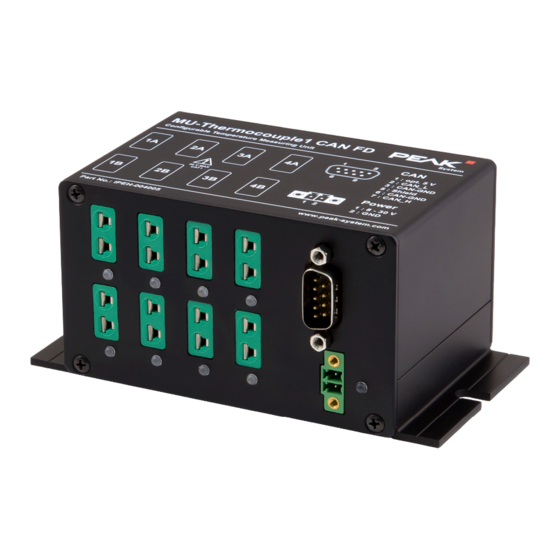
- Page 1 MU-Thermocouple1 CAN FD Configurable System for Temperature Measurement with CAN FD Interface User Manual Document version 1.0.0 (2021-05-05)
- Page 2 K (green). Versions with other thermocouple types are identical in the housing design. PCAN® is a registered trademark of PEAK-System Technik GmbH. CiA®, CANopen®, and CANopen FD® are registered EU trademarks of CAN in Automation e.V.
-
Page 3: Table Of Contents
MU-Thermocouple1 CAN FD – User Manual Contents Introduction Properties at a Glance Prerequisites Scope of Supply Connectors and Status LEDs Power Supply D-Sub Connector for CAN (FD) Thermocouple Inputs Status LEDs Operation Safety Instructions Operation with Default Configuration 3.2.1 CAN Data 3.2.2 Status LEDs Measurement Accuracy... - Page 4 MU-Thermocouple1 CAN FD – User Manual Hardware Modifications Device ID Internal Termination Firmware Transfer Technical Specifications Appendix A CE Certificate Appendix B Dimension Drawings...
-
Page 5: Introduction
MU-Thermocouple1 CAN FD – User Manual Introduction With the MU-Thermocouple1 CAN FD, measurement data of thermocouples is captured, preprocessed, and transmitted via CAN FD. The temperature is measured via 8 connectors which are specified for the temperature measuring ranges J, K or T, depen- ding on the product version. - Page 6 MU-Thermocouple1 CAN FD – User Manual Measurement accuracy: 0.2 % or 1 K Accuracy of the reference temperature sensors at +25 °C ambient temperature: typically ±0.5 K, maximum ±1.0 K Maximum resolution of temperature data: 1/16 °C High-speed CAN connection (ISO 11898-2) for data transfer and configuring •...
-
Page 7: Prerequisites
Computer with Windows 10, 8.1 (32/64-bit) Configuration software Thermocouple FD Configuration for Windows PC-CAN interface from PEAK-System. On delivery, the CAN connection is preconfigured with 500 kbit/s. CAN cabling between the CAN interface and the measuring unit with proper termination (120 Ohm on each end of the CAN bus) -
Page 8: Connectors And Status Leds
MU-Thermocouple1 CAN FD – User Manual Connectors and Status LEDs Top of the housing Connections on the front... -
Page 9: Power Supply
MU-Thermocouple1 CAN FD – User Manual Power Supply The measuring unit is operated with 12 V DC, 8 to 30 V are possible. The connection is done with the supplied mating connector (2-pole, type: Phoenix Contact MC1,5/2-STF-3,81) for fastening cable strands. -
Page 10: Thermocouple Inputs
MU-Thermocouple1 CAN FD – User Manual Tip: We recommend adding termination at the CAN cabling, for example with termination adapters (e.g. PCAN-Term). Thus, CAN nodes can be flexibly connected to the bus. Thermocouple Inputs The connection is done with 2-pin Mini connectors for thermo- couples according to DIN EN 50212. -
Page 11: Status Leds
MU-Thermocouple1 CAN FD – User Manual Status LEDs The device has status LEDs for each of the eight thermocouple inputs as well as for the power supply. LED Indication Meaning Thermocouple Lights red An intact thermocouple is connected. inputs If the corresponding LED does not light up, (configurable) despite the thermocouple being connected, the cable connection or the thermocouple... -
Page 12: Operation
MU-Thermocouple1 CAN FD – User Manual Operation Safety Instructions Attention! Danger due to electric shock! Risk of destroying the measuring unit! You may only measure temperatures on energized parts when these are not directly connected with the mains voltage (measuring category CAT I). The measuring unit must not be used in the measuring categories CAT II, CAT III, or CAT IV. -
Page 13: Can Data
MU-Thermocouple1 CAN FD – User Manual 3.2.1 CAN Data With the default configuration the measuring values of the eight measuring channels and the measuring values of the four reference temperature sensors are transmitted via CAN as follows: Property Value CAN IDs 100h, 101h, 102h Data bytes 2 per measuring channel or reference temperature... -
Page 14: Status Leds
MU-Thermocouple1 CAN FD – User Manual 3.2.2 Status LEDs With the default configuration the status LEDs for the thermocouple inputs are preconfigured according to the following table: LED Indication Meaning Thermocouple Lights red An intact thermocouple is connected. inputs If the corresponding LED does not light up, despite the thermocouple being connected, the cable connection or the thermocouple may be broken. -
Page 15: Measurement Accuracy
MU-Thermocouple1 CAN FD – User Manual Measurement Accuracy The absolute measurement accuracy is based on the internal measurement electronics, the reference temperature sensors, and the thermocouples. Note: If an absolute temperature value and a percentage value are specified for a measurement error, the larger measurement error or the largest error deviation regarding to the measurement result applies. -
Page 16: Measurement Error Due To Thermocouples
MU-Thermocouple1 CAN FD – User Manual ±3 K at ambient temperature from -40 to 125 °C (device is specified up to 85 °C) Note: The ambient temperature should change slowly so that the contact point of the thermocouple in the socket actually corresponds to the measured reference temperature. -
Page 17: Example For Determining The Total Accuracy
MU-Thermocouple1 CAN FD – User Manual Example for Determining the Total Accuracy The following data is assumed for the example: Thermocouple type = J, class 1 Ambient temperature = 40 °C Measured temperature = 100 °C Measurement Errors due to Measurement Electronics The measurement error due to measurement electronics is 1 K or 0.2 % of the measured value. - Page 18 MU-Thermocouple1 CAN FD – User Manual The larger measurement error applies. In this case, the resulting measurement error is 1.5 K. Total Accuracy The total accuracy results from the measurement error components of the measurement electronics (1 K), reference temperature sensors (1 K), and the thermocouples (1.5 K): Total accuracy = 1 K + 1 K + 1.5 K...
-
Page 19: Configuration Software
MU-Thermocouple1 CAN FD – User Manual Configuration Software Data processing, message transmission, and LED indication of the measuring unit MU-Thermocouple1 CAN FD are set up with the free Windows software Thermocouple FD Configuration. The configure- tion created on the computer is transferred via the CAN bus to the device which then runs as an independent CAN node. -
Page 20: Prerequisites
LEDs Export of CAN message and data configuration as a Symbol or CANdb file Transmission of configuration data via CAN (PEAK CAN interface required) Selective configuration of several devices in a CAN network based on the device ID Prerequisites Computer with Windows 10, 8.1 (32/64-bit) -
Page 21: Downloading And Starting The Software
The final transfer of the configura- tion requires a correct connection via CAN. Do the following to establish the CAN connection: Connect your PC-CAN interface from PEAK-System with your computer. Establish a correct CAN cabling between the CAN interface and the measuring unit with proper termination (120 Ohm on each end of the CAN bus). -
Page 22: Hardware Modifications
MU-Thermocouple1 CAN FD – User Manual Hardware Modifications For special applications, various modifications can be done on the circuit board of the MU-Thermocouple1 CAN FD: Changing the device ID to enable the configuration of several measuring units connected to the same CAN bus: chapter 6.1 below. - Page 23 MU-Thermocouple1 CAN FD – User Manual Pull the board with the D-Sub connector out of the connec- tors of the motherboard. You can also remove the entire board from the case. Locate the rotary switch on the board using the following illustration: Set the desired rotary switch position.
-
Page 24: Internal Termination
MU-Thermocouple1 CAN FD – User Manual Internal Termination The CAN bus termination for the CAN connection can be set with the switch block on the board. By default, the switch is set to off. Tip: We recommend adding termination at the CAN cabling, for example with termination adapters (e.g. - Page 25 MU-Thermocouple1 CAN FD – User Manual Set the desired switch position. Switch Internal Termination Position none (default) 120 Ω between CAN_L and CAN_H Carefully plug the D-Sub board back into the connections provided for it on the motherboard. Place the housing cover and screw it with the two upper screws of the back panel.
-
Page 26: Firmware Transfer
MU Thermocouple CAN FD. The firmware upload is done via a CAN bus with the Windows program PEAK-Flash. Do the following to transfer a new firmware with PEAK-Flash: Connect the device to the power supply. The power LED lights green. - Page 27 CAN bus with the appropriate bit rate exists. 11. Click Next. 12. Select the Embedded Firmware or the Firmware File radio button. Embedded Firmware uses the firmware embedded in PEAK- Flash to update the device.
- Page 28 MU-Thermocouple1 CAN FD – User Manual Firmware File uses a custom firmware file (*.bin) to update the device. 13. Click Next. The Ready to Flash dialog appears. 14. Click Start to transfer the new firmware to the MU-Thermocouple1 CAN FD. The Flashing dialog appears.
-
Page 29: Technical Specifications
MU-Thermocouple1 CAN FD – User Manual Technical Specifications Connectors Power Phoenix mating connector , 2-pole, pitch 3.81 mm CAN (FD) D-Sub (m), 9 pins Pin assignment according to specification CiA ® 303-1 Thermocouple Inputs 8 x Mini sockets (DIN EN 50212) Power Supply Operating voltage 8 -30 V DC... - Page 30 MU-Thermocouple1 CAN FD – User Manual CAN (FD) Supported bit timing values Nominal Data Prescaler (BRP) 1 … 512 1 … 32 Time Segment 1 (TSEG1) 1 … 256 1 … 32 Time Segment 2 (TSEG2) 1 … 128 1 … 16 Synch.
- Page 31 (based on Arm Cortex Clock frequency 160 MHz 200 kByte on-chip SRAM Firmware upload via CAN with PEAK-Flash (PCAN interface required) Measures Dimensions 130.5 x 59.5 x 73 mm (W x H x D) See also dimensional drawing in Appendix B Weight...
-
Page 32: Appendix Ace Certificate
MU-Thermocouple1 CAN FD – User Manual Appendix A CE Certificate... -
Page 33: Appendix B Dimension Drawings
MU-Thermocouple1 CAN FD – User Manual Appendix B Dimension Drawings Dimension drawing MU-Thermocouple1 CAN FD The figures do not correspond to the original size. - Page 34 MU-Thermocouple1 CAN FD – User Manual Dimension drawing Mini thermocouple plug (dimensions in mm) The figures do not correspond to the original size.
Need help?
Do you have a question about the IPEH-004005-J and is the answer not in the manual?
Questions and answers