Table of Contents
Advertisement
Advertisement
Chapters
Table of Contents

Related Manuals for Peak dca55


Summary of Contents for Peak dca55
- Page 1 Peak Atlas DCA Semiconductor Component Analyser Model DCA55 Designed and manufactured with pride in the UK User Guide © Peak Electronic Design Limited 2000/2014 In the interests of development, information in this guide is subject to change without notice - E&OE...
-
Page 2: Table Of Contents
Atlas DCA User Guide September 2014 – Rev 11 Want to use it now? We understand that you want to use your Atlas DCA right now. The unit is ready to go and you should have little need to refer to this user guide, but please make sure that you do at least take a look at the notices on page 4! Contents... -
Page 3: Introduction
Atlas DCA User Guide September 2014 – Rev 11 Introduction The Peak Atlas DCA is an intelligent semiconductor analyser that offers great features together with refreshing simplicity. The Atlas DCA brings a world of component data to your fingertips. Summary Features: •... -
Page 4: Important Considerations
Atlas DCA User Guide September 2014 – Rev 11 Important Considerations Please observe the following guidelines: This instrument must NEVER be connected to powered • equipment/components or equipment/components with any stored energy (e.g. charged capacitors). Failure to comply with this warning may result in personal injury, damage to the equipment under test, damage to the Atlas DCA and invalidation of the manufacturer’s warranty. - Page 5 If the component has only two terminals, then any pair of the three test probes can be used. The Atlas DCA will start component Atlas DCA55 Rx.x analysis when the on-test button is is analysing..
- Page 6 Atlas DCA User Guide September 2014 – Rev 11 If the Atlas DCA cannot detect any No component component between any of the test probes, the following message will be detected displayed: If the component is not a supported component type, a faulty component or Unknown/Faulty a component that is being tested in- component...
-
Page 7: Diodes
Atlas DCA User Guide September 2014 – Rev 11 Diodes The Atlas DCA will analyse almost any type of diode. Any pair of the three test clips can be connected to the diode, any way round. If the unit detects a single diode, the following message will be displayed: scroll-off Pressing... -
Page 8: Diode Networks
Atlas DCA User Guide September 2014 – Rev 11 Diode Networks The Atlas DCA will intelligently identify popular types of three terminal diode networks. For three terminal devices such as SOT-23 diode networks, the three test clips must all be connected, any way round. The instrument will identify the type of diode network and then display information regarding each detected diode in sequence. -
Page 9: Leds
Atlas DCA User Guide September 2014 – Rev 11 LEDs An LED is really just another type of diode, however, the Atlas DCA will determine that an LED or LED network has been detected if the measured forward voltage drop is larger than 1.5V. -
Page 10: Bicolour Leds
Atlas DCA User Guide September 2014 – Rev 11 Bicolour LEDs Bicolour LEDs are automatically identified. If your LED has 3 leads then ensure they are all connected, in any order. A two terminal bicolour LED consists of two LED chips which are connected in inverse parallel within the LED body. -
Page 11: Bipolar Junction Transistors (Bjts)
Atlas DCA User Guide September 2014 – Rev 11 Bipolar Junction Transistors (BJTs) Bipolar Junction Transistors are simply “conventional” transistors, although variants of these do exist such as Darlingtons, diode protected (free-wheeling diode), resistor shunted types and combinations of these types. All of these variations are automatically identified by the Atlas DCA. - Page 12 Atlas DCA User Guide September 2014 – Rev 11 Pressing the scroll-off button will result in the transistor’s pinout being displayed. Here, the instrument has identified that RED GREEN BLUE the Base is connected to the Red test clip, the Collector is connected to the Base Coll Emit Green test clip and the Emitter is connected to the Blue test clip.
- Page 13 Atlas DCA User Guide September 2014 – Rev 11 Additionally, many Darlingtons and a few non-Darlington transistors also have a resistor shunt network between the base and emitter of the device. The Atlas DCA can detect the resistor shunt if it has a resistance of typically less than 60kΩ.
- Page 14 Atlas DCA User Guide September 2014 – Rev 11 Faulty or Very Low Gain Transistors Faulty transistors that exhibit very low gain may cause the Atlas DCA to only identify one or more diode junctions within the device. This is because NPN transistors consist of a structure of junctions that behave like a common anode diode network.
- Page 15 Atlas DCA User Guide September 2014 – Rev 11 Current Gain (h The DC current gain (h ) is displayed I -I C Cleak h FE = after any special transistor features have been displayed. = leakage Cleak current) I C =2.5mA DC current gain is simply the ratio of the collector current (less leakage) to the base current for a particular operating...
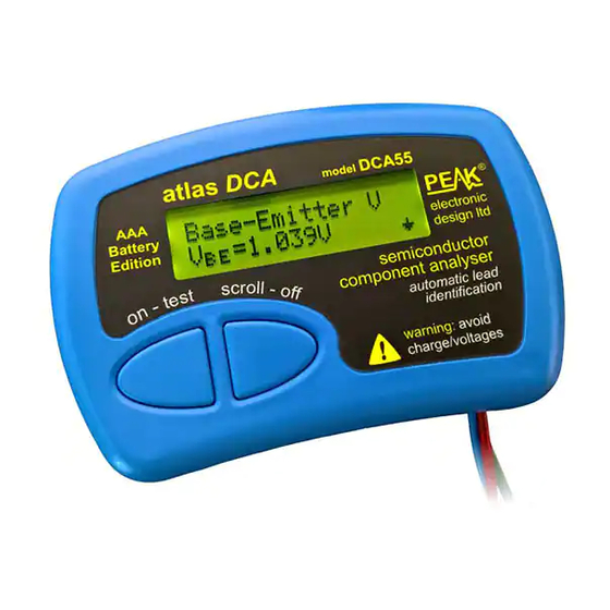
- Page 16 Atlas DCA User Guide September 2014 – Rev 11 Base-Emitter Voltage Drop The DC characteristics of the base-emitter junction are displayed, both the base-emitter forward voltage drop and the base current used for the measurement. V BE B-E Voltage Vbe=0.77V The forward base-emitter voltage drop can aid in the identification of silicon or germanium devices.
- Page 17 Atlas DCA User Guide September 2014 – Rev 11 Collector Leakage Current The collector current that takes place when no base current is flowing is referred to as Leakage Current. Most modern transistor exhibit Leakage extremely low values of leakage I B = 0 current, often less than 1µA, even for very high collector-emitter voltages.
-
Page 18: Digital Transistors
Atlas DCA User Guide September 2014 – Rev 11 Digital Transistors Digital transistors aren’t really digital, they can act in both a linear or fully on/off mode. They’re called “digital transistors” because they can be driven directly to digital outputs without the need for current limiting resistors. -
Page 19: Enhancement Mode Mosfets
Atlas DCA User Guide September 2014 – Rev 11 Enhancement Mode MOSFETs MOSFET stands for Metal Oxide Semiconductor Field Effect Transistor. Like bipolar transistors, MOSFETs are available in two main types, N-Channel and P-Channel. Most modern MOSFETs are of the Enhancement Mode type, meaning that the bias of the gate-source voltage is always positive (For N-Channel types). -
Page 20: Depletion Mode Mosfets
Atlas DCA User Guide September 2014 – Rev 11 Depletion Mode MOSFETs The fairly rare Depletion Mode MOSFET is very similar to the conventional Junction FET (JFET) except that the gate terminal is insulated from the other two terminals. The input resistance of these devices can typically be greater than 1000MΩ... -
Page 21: Junction Fets (Jfets)
Atlas DCA User Guide September 2014 – Rev 11 Junction FETs (JFETs) Junction FETs are conventional Field Effect Transistors. The voltage applied across the gate-source terminals controls current between the drain and source terminals. N-Channel JFETs require a negative voltage on their gate with respect to their source, the more negative the voltage, the less current can flow between the drain and source. -
Page 22: Thyristors (Scrs) And Triacs
Atlas DCA User Guide September 2014 – Rev 11 Thyristors (SCRs) and Triacs Sensitive low power thyristors (Silicon Controlled Rectifiers - SCRs) and triacs that require gate currents and holding currents of less than 5mA can be identified and analysed with the Atlas DCA. Thyristor terminals are the anode, Sensitive or low cathode and the gate. -
Page 23: Atlas Dca User Guide September 2014 – Rev
September 2014 – Rev 11 Care of your Atlas DCA The Peak Atlas DCA should provide many years of service if used in accordance with this user guide. Care should be taken not to expose your unit to excessive heat, shock or moisture. Additionally, the battery should be replaced at least every 12 months to reduce the risk of leak damage. -
Page 24: Self Tests
Atlas DCA User Guide September 2014 – Rev 11 Self Test Procedure Each time the Atlas DCA is powered up, a self test procedure is performed. In addition to a battery voltage test, the unit measures the performance of many internal functions such as the voltage and current sources, amplifiers, analogue to digital converters and test lead multiplexers. -
Page 25: Appendix A - Technical Specifications
Atlas DCA User Guide September 2014 – Rev 11 Appendix A - Technical Specifications All values are at 25°C unless otherwise specified. Note Parameter Peak test current into S/C -5.5mA 5.5mA Peak test voltage across O/C -5.1V 5.1V Transistor gain range (h... -
Page 26: Appendix B - Warranty Information
Appendix B – Warranty Information Peak Satisfaction Guarantee If for any reason you are not completely satisfied with the Peak Atlas DCA within 14 days of purchase you may return the unit to your distributor. You will receive a refund covering the full purchase price if the unit is returned in perfect condition. -
Page 27: Appendix C - Disposal Information
More details can be obtained from your national WEEE recycling agency. If in doubt, you may send your Peak Product to us for safe and environmentally responsible disposal. At Peak Electronic Design Ltd we are committed to continual product development and improvement. - Page 28 Peak Atlas LCR Passive Component Analyser Model LCR40 Designed and manufactured with pride in the UK User Guide © Peak Electronic Design Limited 2002/2012 In the interests of development, information in this guide is subject to change without notice - E&OE...
- Page 29 Atlas LCR User Guide April 2012 – Rev 5 Want to use it now? We understand that you want to use your Atlas LCR right now. The unit is ready to go and you should have little need to refer to this user guide, but please make sure that you read through pages 4-6! Contents Page...
-
Page 30: Introduction
Atlas LCR User Guide April 2012 – Rev 5 Introduction The Atlas LCR is an advanced instrument that greatly simplifies the testing of passive components. Traditional LCR bridges are inherently complex and very time consuming to use. The Atlas LCR does everything automatically, it tells you the component type in addition to component value data. -
Page 31: Important Notices
Atlas LCR User Guide April 2012 – Rev 5 Important Notices WARNING: This instrument must NEVER be connected to powered equipment/components or equipment/components with any stored energy (e.g. charged capacitors). Failure to comply with this warning may result in personal injury, damage to the equipment under test, damage to the Atlas LCR and invalidation of the manufacturer's warranty. -
Page 32: Using Your Atlas Lcr
Atlas LCR User Guide April 2012 – Rev 5 Using your Atlas LCR Normal Use The Atlas LCR performs its component analysis before the results are displayed. Therefore, once the analysis has completed, the probes can be disconnected from the component. Analysis itself only takes a few seconds and you can choose to start the analysis after a 5 second delay or immediately. -
Page 33: Probe Compensation
Atlas LCR User Guide April 2012 – Rev 5 Probe Compensation If you change the probes on your Atlas LCR, it is good practice to run through the short compensation procedure. This ensures that the probes' own inductance, capacitance and resistance is automatically taken into account for subsequent measurements. -
Page 34: Testing Inductors
Atlas LCR User Guide April 2012 – Rev 5 Testing Inductors The Atlas LCR is designed to analyse most inductors, coils and chokes. Inductor test frequency: The test frequency that the Atlas LCR uses will be automatically selected from 1kHz, 15kHz or 200kHz. The following table shows the test frequencies used for various inductance ranges: Inductance Range Test Frequency Used... -
Page 35: Testing Capacitors
Atlas LCR User Guide April 2012 – Rev 5 Testing Capacitors The Atlas LCR uses two different methods to analyse capacitors, AC impedance analysis for low value capacitors (less than about 1µF) and DC charge analysis for larger capacitors (about 1µF to 10,000µF). Capacitors (particularly electrolytics) can store enough charge that may cause damage to the LCR. - Page 36 Atlas LCR User Guide April 2012 – Rev 5 Low Value Capacitors There is a vast range of low value capacitors available. Types include ceramic, polyester, polystyrene and mylar dielectric capacitors. Generally, low value capacitors tend to be unpolarised. Minimum capacitance resolution is about 0.2pF.
- Page 37 Atlas LCR User Guide April 2012 – Rev 5 Large Capacitors Capacitors larger than about 1µF are treated differently, instead of being tested with an AC signal, they are tested with a DC signal. This is confirmed in the “Test frequency” screen. Please be patient when testing large value capacitors, it may take several seconds depending on the capacitance.
-
Page 38: Testing Resistors
0.3 . Resistance is measured using a DC signal with a peak voltage of 1V (across an open circuit) and a peak current of about 3mA (through a short circuit). Resistance... -
Page 39: Taking Care Of Your Atlas Lcr
Although the unit may continue to operate following a low battery warning, measurements may be adversely affected. New batteries can be purchased from many retailers and directly from Peak Electronic Design Ltd or an authorised agent. Battery types: Suitable battery types include 23A, V23A, GP23A, MN21 or a good quality 12V alkaline equivalent as used in many test instruments and automotive remote key fobs. -
Page 40: Self Tests
It is possible that a temporary condition caused the failure and restarting the unit may clear the problem. If the fault persists please contact Peak Electronic Design Ltd or an authorised agent with details of the error message for further advice. -
Page 41: Appendix A - Accessories
Fitting is easy: the tweezers are terminated in the standard Atlas LCR probe connectors. Other Probe Accessories Many different probe types are available, specially made for your Atlas LCR. Contact Peak Electronic Design Ltd or an authorised agent for more details. Page 14... -
Page 42: Appendix B - Component Identification
Atlas LCR User Guide April 2012 – Rev 5 Appendix B - Component Identification It is important to appreciate that the Atlas LCR can only decide on the identity of the component under test using results of the electrical tests that it performs on the component. - Page 43 Atlas LCR User Guide April 2012 – Rev 5 Capacitor Detection The Atlas LCR will tell you that you have a capacitor if the following criteria are satisfied: 1. If the measured DC resistance is higher than 10M , even if the measured capacitance is very low (such as open probes).
-
Page 44: Appendix C - Technical Specifications
0.5pF accuracy Typically ±1.5% ±1.0pF 1,2,5 range Inductance resolution 0.4 H 0.8 H accuracy Typically ±1.5% ±1.6 H 1,2,4 Peak test voltage (across O/C) -1.05V +1.05V Peak test current (thru S/C) -3.25mA +3.25mA 1kHz -1.5% ±1% +1.5% Test frequency 14.925kHz -1.5%... -
Page 45: Appendix D - Troubleshooting
Atlas LCR User Guide April 2012 – Rev 5 Appendix D – Troubleshooting Problem Possible Solution Capacitance measured when probes are open circuit is not Perform a probe compensation. close to zero (±1.0pF). Resistance and/or inductance measured when probes are Perform a probe compensation. -
Page 46: Appendix E - Warranty Information
Appendix E – Warranty Information Peak Satisfaction Guarantee If for any reason you are not completely satisfied with the Peak Atlas LCR within 14 days of purchase you may return the unit to your distributor. You will receive a refund covering the full purchase price if the unit is returned in perfect condition. -
Page 47: Appendix F - Disposal Information
More details can be obtained from your national WEEE recycling agency. If in doubt, you may send your Peak Product to us for safe and environmentally responsible disposal. At Peak Electronic Design Ltd we are committed to continual product development and improvement.
Need help?
Do you have a question about the dca55 and is the answer not in the manual?
Questions and answers