Table of Contents
Advertisement
Quick Links
Advertisement
Table of Contents

Related Manuals for Peak Atlas DCA55


Summary of Contents for Peak Atlas DCA55
- Page 1 Atlas DCA55 Semiconductor Component Analyser Model DCA55 (Firmware: 4.1) Designed and manufactured with pride in the UK User Guide © Peak Electronic Design Limited 2000/2021 In the interests of development, information in this guide is subject to change without notice. E&OE...
-
Page 2: Table Of Contents
DCA55 User Guide November 2021 – Rev 14 Want to use it now? We understand that you want to use your DCA55 right now. The unit is ready to go and you should have little need to refer to this user guide, but please make sure that you do at least take a look at the notices on page 4! Contents... -
Page 3: Introduction
DCA55 User Guide November 2021 – Rev 14 Introduction The Peak Atlas DCA55 is an intelligent semiconductor analyser that offers great features together with refreshing simplicity. The DCA55 brings a world of component data to your fingertips. Summary Features: Automatic component type identification ... -
Page 4: Important Considerations
DCA55 User Guide November 2021 – Rev 14 Important Considerations Please observe the following guidelines: This instrument must NEVER be connected to powered equipment/components or equipment/components with any stored energy (e.g. charged capacitors). Failure to comply with this warning may result in personal injury, damage to the equipment under test, damage to the DCA55 and invalidation of the manufacturer’s warranty. -
Page 5: Analysing Semiconductors
If the component has only two terminals, then any pair of the three test probes can be used. The DCA55 will start component Peak Atlas DCA analysis when the on-test button is model DCA55 Rx.x pressed. - Page 6 DCA55 User Guide November 2021 – Rev 14 If the DCA55 cannot detect any No component component between any of the test probes, the following message will be detected displayed: If the component is not a supported component type, a faulty component or Unknown/Faulty a component that is being tested in- component...
-
Page 7: Diodes
DCA55 User Guide November 2021 – Rev 14 Diodes The DCA55 will analyse almost any type of diode. Any pair of the three test clips can be connected to the diode, any way round. If the unit detects a single diode, the following message will be displayed: Pressing the scroll-off button will then Diode or diode... -
Page 8: Diode Networks
DCA55 User Guide November 2021 – Rev 14 Diode Networks The DCA55 will intelligently identify popular types of three terminal diode networks. For three terminal devices such as SOT-23 diode networks, the three test clips must all be connected, any way round. The instrument will identify the type of diode network and then display information regarding each detected diode in sequence. -
Page 9: Leds
DCA55 User Guide November 2021 – Rev 14 LEDs An LED is really just another type of diode, however, the DCA55 will determine that an LED or LED network has been detected if the measured forward voltage drop is larger than 1.5V. -
Page 10: Bicolour Leds
DCA55 User Guide November 2021 – Rev 14 Bicolour LEDs Bicolour LEDs are automatically identified. If your LED has 3 leads then ensure they are all connected, in any order. A two terminal bicolour LED consists of two LED chips which are connected in inverse parallel within the LED body. -
Page 11: Bipolar Junction Transistors (Bjts)
DCA55 User Guide November 2021 – Rev 14 Bipolar Junction Transistors (BJTs) Bipolar Junction Transistors are simply “conventional” transistors, although variants of these do exist such as Darlingtons, diode protected (free-wheeling diode), resistor shunted types and combinations of these types. All of these variations are automatically identified by the DCA55. - Page 12 DCA55 User Guide November 2021 – Rev 14 Transistor Special Features Many modern transistors contain additional special features. If the DCA55 has detected any special features, then the details of these features are displayed next after pressing the scroll-off button. If there are no special features detected then the next screen will be the transistor’s current gain.
- Page 13 DCA55 User Guide November 2021 – Rev 14 Additionally, many Darlingtons and a few non-Darlington transistors also have a resistor shunt network between the base and emitter of the device. The DCA55 can detect the resistor shunt if it has a resistance of typically less than 60k.
- Page 14 DCA55 User Guide November 2021 – Rev 14 Faulty or Very Low Gain Transistors Faulty transistors that exhibit very low gain may cause the DCA55 to only identify one or more diode junctions within the device. This is because NPN transistors consist of a structure of junctions that behave like a common anode...
- Page 15 DCA55 User Guide November 2021 – Rev 14 Current Gain (h The DC current gain (h ) is displayed I -I C Cleak h FE = after any special transistor features have been displayed. = leakage Cleak current) I C =2.5mA DC current gain is simply the ratio of the collector current (less leakage) to the base current for a particular operating...
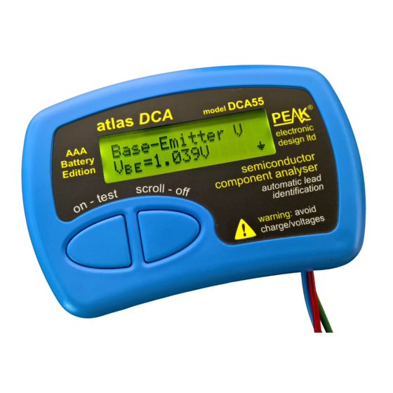
- Page 16 DCA55 User Guide November 2021 – Rev 14 Base-Emitter Voltage Drop The DC characteristics of the base-emitter junction are displayed, both the base-emitter forward voltage drop and the base current used for the measurement. V BE The forward base-emitter voltage drop B-E Voltage can aid in the identification of silicon or germanium...
- Page 17 DCA55 User Guide November 2021 – Rev 14 Collector Leakage Current The collector current that takes place when no base current is flowing is referred to as Leakage Current (I Most modern transistor exhibit Leakage I B = 0 extremely low values of leakage current, often less than 1μA, even for very high collector-emitter voltages.
-
Page 18: Digital Transistors
DCA55 User Guide November 2021 – Rev 14 Digital Transistors Digital transistors aren’t really digital, they can act in both a linear or fully on/off mode. They’re called “digital transistors” because they can be driven directly by digital outputs without the need for base current limiting resistors. -
Page 19: Enhancement Mode Mosfets
DCA55 User Guide November 2021 – Rev 14 Enhancement Mode MOSFETs MOSFET stands for Metal Oxide Semiconductor Field Effect Transistor. Like bipolar transistors, MOSFETs are available in two main types, N-Channel and P-Channel. Most modern MOSFETs are of the Enhancement Mode type, meaning that the bias of the gate-source voltage is always positive (For N-Channel types). -
Page 20: Depletion Mode Mosfets
DCA55 User Guide November 2021 – Rev 14 Depletion Mode MOSFETs The fairly rare Depletion Mode MOSFET is very similar to the conventional Junction FET (JFET) except that the gate terminal is insulated from the other two terminals. The input resistance of these devices can typically be greater than 1000M... -
Page 21: Junction Fets (Jfets)
DCA55 User Guide November 2021 – Rev 14 Junction FETs (JFETs) Junction FETs are conventional Field Effect Transistors. The voltage applied across the gate-source terminals controls current between the drain and source terminals. N-Channel JFETs require a negative voltage on their gate with respect to their source, the more negative the voltage, the less current can flow between the drain and source. -
Page 22: Thyristors (Scrs) And Triacs
DCA55 User Guide November 2021 – Rev 14 Thyristors (SCRs) and Triacs Sensitive low power thyristors (Silicon Controlled Rectifiers - SCRs) and triacs that require gate currents and holding currents of less than 5mA can be identified and analysed with the DCA55. Thyristor terminals are the anode, Sensitive or low cathode and the gate. -
Page 23: Taking Care Of Your Dca55
After fitting of the new battery, carefully place the rear cover in position, taking care not to trap the test wires. Do not over-tighten the screws. Replacement batteries are available directly from Peak Electronic Design Limited and many good electronic/automotive outlets. Page 23... -
Page 24: Self Tests
DCA55 User Guide November 2021 – Rev 14 Self Test Procedure Each time the DCA55 is powered up, a self test procedure is performed. In addition to a battery voltage test, the unit measures the performance of many internal functions such as the voltage and current sources, amplifiers, analogue to digital converters and test lead multiplexers. -
Page 25: Appendix A - Technical Specifications
DCA55 User Guide November 2021 – Rev 14 Appendix A - Technical Specifications All values are at 20C unless otherwise specified. Note Parameter Bipolar Junction Transistors Measurable gain range (h 20000 Gain resolution Gain accuracy ±3% ±4 h Gain jitter (3σ) ±0.2% Gain test voltage V 2.0V... - Page 26 Parameter JFETs Drain-source test current 0.5mA 5.5mA SCRs/Triacs Gate test current 4.5mA Load test current 5.0mA General Specifications Peak test current into S/C -5.5mA 5.5mA Peak test voltage across O/C -5.1V 5.1V Short circuit threshold 5 10 15 Analysis duration...
- Page 27 DCA55 User Guide November 2021 – Rev 14 This page is intentionally blank. Appendix B is on the rear cover of this user guide. Page 27...
-
Page 28: Appendix B - Statutory Information
More details can be obtained from your national WEEE recycling agency. At Peak Electronic Design Ltd we are committed to continual product development and improvement. The specifications of our products are therefore subject to change without notice.
Need help?
Do you have a question about the Atlas DCA55 and is the answer not in the manual?
Questions and answers