Table of Contents
Advertisement
Quick Links
Advertisement
Chapters
Table of Contents

Related Manuals for ABB IRB 2000


Summary of Contents for ABB IRB 2000
- Page 1 A B B Product Manual, IRB 2000 3HAB 0007-2 ASEA BROWN BOVERI Configuration List Description IRB 2000 3HAB 0001-2 Safety 3HAB 0001-8 Installation IRB 2000 3HAB 0003-2 Installation S3 3HAB 0003-8 Maintenance IRB 2000 3HAB 0005-2 Additional Documents (Option, RSI)
- Page 2 Product Manual IRB 2000 3HAB 0007- 2 January 1993/M93 Jk It It ABB Robotics Products ASEA BROWN BOVERI...
- Page 3 AB's written permission, and the contents thereof must not be imparted to a third party nor be used for any unauthorized purpose. Contravention will be prosecuted. Additional copies of this document may be obtained from ABB Robotics Products AB at its then current charge.
- Page 4 "Configuration List" ar en individueli specifikation Programming Manual! av det levererade robotsystemet avseende upp- Computer link docum byggnad och omfattning. Vid leveransen fran ABB Robotics finns det kompletta dokumentet inlagt i styrskapet. Tested according to inspection provision 3HAA 3916-B Date Name...
- Page 5 Description IRB 2000 3HAB 0001-2 January 1993/M93 A It It #*IPIP ABB Robotics Products ASEA BROWN BOVERI...
- Page 6 ABB Robotics Products AB. ABB Robotics Products AB assumes no responsibility for any errors that may appear in this document. In no event shall ABB Robotics Products AB be liable for incidental or consequential damages arising from use of this document or of the software and hardware described in this document.
-
Page 7: Table Of Contents
CONTENTS Chapter Page 1 INTRODUCTION 2 CHARACTERISTICS, IRB 2000 SYSTEM DESCRIPTION 3.1 Manipulator 3.2 Control cabinet OPERATION/PROGRAMMING 4.1 Control panel 4.1.1 Remote control Programming unit Programming 4.3.1 Program design 4.3.2 Movements 4.3.3 Programmable functions 4.3.4 Editing functions 4.3.5 Manually controlled functions 4.3.6... - Page 8 Description 1KB 2000...
-
Page 9: Introduction
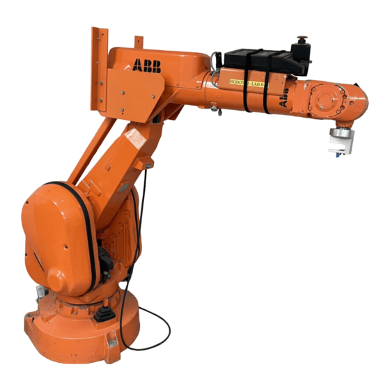
1KB 2000 is a six-axes robot with a large work volume and is primarily intended for arc welding and glueing/sealing. IRB 2000 is also suitable for applications such as assembly, water jet cutting, laser cutting, material handling and stud welding. - Page 10 Description 1KB 2000...
-
Page 11: Characteristics, Irb 2000
CHARACTERISTICS, IRB 2000 Capabilities The IRB 2000 handles a load of up to 10 kg within a wide working range, accurately and rapidly. The slendemess and dexterity of its arm system gives high accessability. Its designe permits installation of the same robot on the floor or inverted. - Page 12 Description 1KB 2000...
- Page 13 Operator communication, programming and manual running is performed via a portable programming unit. Programming can also be performed off-line via a terminal and an ABB Robotics Off-line Programming Package. CONTROL UNIT Programming unit...
-
Page 14: Manipulator
Manipulator The Manipulator can in one version be used for either floor mounting or inverted sustpension. Exeptional for this design is: • small pedestal turning radius slender arm system. Serviceability Extensive effort has been put into making the robot easily serviceable and therefore fault can be done in minutes by service personnel. - Page 15 Movement structure The robot's movement pattern can briefly be described as follows (see also the figure below). Axisl(C) Turning of the complete mechanical unit arm system. Axis 2 (B) Forward and reverse movement of the lower arm. Axis 3 (A) Up and down movement of the upper arm.
-
Page 16: Control Cabinet
Control system Control panel Main functions for robot operation. Programming unit All functions for robot operation and programming. Built-in system test. Floppy disk unit Handles storing/loading of data on floppy disk. Winchester memory Handles storing/loading of data in a mass memory. (option) Duty time counter Recording duty time. - Page 17 Eletronic components Computer board • Contains four microprocessors: Main computer - for overall control. Servo computer - for control of servo functions and robot movements. - Axis computer - for individual control of robot axes. I/O computer - for control of communication with operator unit, peripheral equipment, host computer (option) and floppy disc unit.
- Page 18 Process connections (option) The system can handle the following input and output signals from the peripheral equipment: • Digital I/O - up to 96 inputs and 96 outputs Requires 1-6 digital I/O boards (option) • Analogue I/O - up to 4 inputs and 4 outputs Requires 1 analogue I/O board (option) •...
- Page 19 Diagnostics The control system is provided with its own built-in diagnostics with the following characteristics: • Test on start-up: - computer board; - programming unit; - monitor (option); - voltage supply unit; - rectifier unit. - location control of I/O boards and drive units •...
- Page 20 Description 1KB 2000...
-
Page 21: Operation/Programming
OPERATION/PROGRAMMING Control panel Using the control panel, operating modes can be selected and the robot can be switched to MOTOR ON or MOTOR OFF. Lamps inside the buttons indicate status and any malfunction. The control panel also includes one of the emergency stop buttons. Lockable switch for selection of operation mode: Program run at maximum speed. -
Page 22: 4.1.1 Remote Control
4.1.1 Remote control • By using the first 8 inputs and outputs on any I/O board the following functions can be remotely controlled: Control Indication (input) (output) MOTOR ON MOTOR OFF Program start Program stop Synchronization From disc Lamp test Prog, unit lock Error Emergency stop... -
Page 23: Programming
I© Fig 4.2 Programming unit Programming 4.3.1 Program design The user memory can contain programs numbered from 0 to 9999. The programs in the user memory together form a program block. The size of each program can be adapted as required, provided that the total quantity of programs fit into the user memory. - Page 24 4.3.2 Movements The operator programs a pattern of movements as a number of subsidiary movements between required positions (point-to-point programming). Each position is programmed by the operator moving the robot to the desired position manually. A specific point, known as the work point or the Tool Centre Point (TCP) moves relative to the robot in a well defined manner.
- Page 25 A Tool Centre Line (TCL) can be created by defining a base point (BASEP) together with the TCP in the wrist-oriented coordinate system. The TCL then constitutes the x-axis in a tool-oriented coordinate system. The TCL is mainly based on the orientation of a tool or a gripper relative to the turn plate and enables a gripper or a tool to be moved parallel to its own configuration.
-
Page 26: Programmable Functions
4.3.3 Programmable functions Position programming instructions • General parameter: - Position accuracy; - Speed, as a percentage of defined absolute speed. • Supplementary parameter: - A position brought: directly from a position register; indirectly from a position register via an address in a numerical register. - Position offset value: stored directly in an instruction;... - Page 27 The various programmable functions are: Search: The robot will serach for an object as it moves towards a programmed position. The search is successful when one of the sensors has found the object.T he result of a search can be used as: •...
- Page 28 In-pos check (if option 481, MH/GL/SW is selected) Used together with soft servo. A conditional jump may be performed as a result of a permitted deviation from the programmed position. SWI (if option 481, MH/GL/SW is selected) SWI (Spot Welding Interface) is a soft ware function for control of an external welding timer.
- Page 29 Program execution: - Pause in program running, defined by: time; input conditions. - Jump in a program: unconditional; conditional; search stop condition. - Program stop. I/O handling (option): - Setting of digital outputs; - Enabling/disabling of direct acting inputs (system I/O); - Transmission of numerical values between I/O and numerical registers.
-
Page 30: Manually Controlled Functions
- Change or definition of the wrist- or tool-oriented coordinates for the TCP; - Direct-acting definition of the TCP; - Erasure of TCP. • Alignment of the tool: (not AW) - With one of the rectangular base coordinate axes; - With a previously stored orientation. Description IRB 2000... - Page 31 Use of system data (system parameters) - Check on or change of a separate parameter value; - Loading of predefined parameter values; - Loading and storing of back-up stored parameter values. Choice of language for information displayed on the programming unit panel. Listing of (option): - Messages from the fault buffer;...
- Page 32 Description 1KB 2000...
-
Page 33: Features
TECHNICAL SPECIFICATION Features All data is valid for IRB 2000 independent of whether the robot is installed standing up or in an inverted position. 5.1.1 Performance Type of movementCsee chapter 3) Working range Max. speed + 179,9° - Axis 1 (C) Rotation movement -179,9°... -
Page 34: Battery Capacity
5.1.3 Battery capacity Computer board aprox. 50000 hours Back-up capacity 3.6 V lithium Battery, type 5 years (if environme Battery expected life-time temp <35° C) Serial measurement board Battery capacity 1000hrs(4Ah) Expected life-time 5 years (<50°C) Recharging time 18 hours Diskette capacity 7 x 32 kword (448 kb Winchester capacity (option) - Page 35 Number of menus 6 standard menus Aids for dialogue Messages from the system Plain language Choice of language for messages English, + 9 selectable Display in programming unit Alphanumeric, 2 rows Number of characters per row Aids for data entry Numerical key pad + 5 multi-function keys 5.15...
- Page 36 IS* flgl J3ZM \535 Pbsi. Fig 5.3 Position of the robot arm in its extreme positions. All dimensions in millimetres. 1KB 2000 Description...
- Page 37 5.1.7 Load diagram A X'(Mn) Fig 5.4 Permitted load as function of the location of the mass centre of gravity, relative to robot mounting flange. Description IRB2000...
- Page 38 Fig 5.5 The cross lined area indicates centre of gravity allowed extra load at the mass point. 1KB 2000 Description...
-
Page 39: Requirements
5.2. Requirements 5.2.1 Environmental requirements Protection standard Cabinet IP 54(NEMA 12) Manipulator IP 54(NEMA 12) Explosive atmosphere The robot shall not be placed and operated within explosive atmospheres. Ambient temperature Manipulator, running + 5° C — + 45° C Control cabinet and programming unit, running + 5°... - Page 40 5.3.2 Dimensional drawings Description 1KB 2000...
- Page 41 _200 _D-D_ Description 1KB 2000...
- Page 42 Dimensional drawing Control cabinet Space required 1100 If the free space (gray zone) around the cabinet is less than 100 mm, a heat exchanger or air conditioner is necessary. View from above Cooling device Front view Pockets for forklift Description 1KB 2000...
-
Page 43: Standards
Standards 5.4.1 General The mechanical robot and the control cabinet have been designed to fulfil the requirements in IEC 204-1 and SS EN 60204. The SS EN 60204 document contains the text from IEC 204-1, but with a number of modifications and supplements common to CENELEC (Comite Europe'en de Normalisation Electrotechnique). - Page 44 Description 1KB 2000...
-
Page 45: Manipulator
SPECIFICATION OF THE ROBOT The options are described below using the same headings as the ones in the specification form. Manipulator Application interface (customer connection) Air and signals to upper arm An integrated air supply system is located within the arms. Connection in the base and outlet in the moving section of the upper arm. - Page 46 Mains supply circuit-breaker Rotary switch as per IEC 204, IEC 337-1, VDE 0113. UL, EN 60204. As an accessory for the rotary switch there is a 20 A circuit breaker, for protection of the main voltage in the cabinet. According to IEC 898, VDE 0660. Fig 6.5 Circuit breaker Flange disconnect switch The control system can be provided with a front-operated flange disconnect switch,...
- Page 47 The following programmable functions also apply to the external axes: Running up to a progam position, including the percentage speed value, with or without stated positional accuracy. • Parallel displacement of the motion pattern with the help of a reference point. The result will be a displacement of the pattern along the work envelope for the axis in question (linear movement), or movement of the motion pattern around the rotation centre (rotating movement).
- Page 48 Excitation voltage 5.7 V/2 kHz I/O CAPACITY I/O units are not included in the basic versions of IRB 2000. In all, there are 6 available I/O slots (max. 5 with option 405 Winchester memory included): • digital I/O, 16 in/16 out, max. 6 units (1 slot per unit) •...
- Page 49 System I/O Contents: Control signals for: • operation of grippers 1 and 2 (outputs) Interrupt signals (inputs): • CALL for sub program 1-5 (inputs) • INTERRUPT PROGRAM • INTERRUPT INSTRUCTION Status signals (outputs) for: MOTOR ON • CYCLE ON • ERROR (error during program running both AUTO and MANUAL) •...
- Page 50 Welding equipment (AW) Signals Signals reserved for welding equipment for the arc welding version (AW). Contents: inputs: - supervision, gas/liquid cooling - supervision, current - wire feed, on - process, off - weaving, off outputs: - voltage, on - wire feed, on - gas, on Resered: 5 inputs + 3 outputs...
- Page 51 I/O map The system is supplied as standard with the above configuration. By using an I/O map inputs and outputs can be individually allocated an optional channel ("mapping") to adapt I/O to the installation. For further information regarding I/O mapping, see the installation manual for S3. I/O ports Series and parallel I/O are available and can be activated from the user program when necessary.
- Page 52 1 current output Output current ±20 mA Load <450 ohm Resolution 20 uA (20/1024 mA) Accuracy 60 A + 0.5% of output current The analogue unit requires separate power supply ±15 V according to one of the following alternatives: • Internal ±15 V supply, not galvanically insulated from the electronics in the control cabinet, only intended for analogue I/O.
- Page 53 This product incorporates a communications link which is licensed under patents and proprietary technology of Allen Bradley Company, Inc.. Allen Bradley Company, Inc. does not warrant or support this product. All warranty and support services for this product are the responsibility of and provided by ABB Robotics Products TYPE OF CONNECTION The control system connections can be adapted to various needs through choices shown below.
- Page 54 the inner rear cabinet wall. Cable contacts are of type DIN 41651. External connection The standard connections to the robot are with 64-pole plug-in connectors DIN 43652 on the outer left-hand side of the control system (seen from the front). 1KB 2000 and 1KB 3000/3200 IRB6000...
- Page 55 Fig 6.8 Option mounting plate Safety signals Safety signals, etc., are connected on a unit (1) on the lower bar. If the option of customer connection (651-656) is selected, these terminals (2) are also placed on the bar furthest down. Analogue signals Analogue signals are connected on a screw terminal unit as fig.
- Page 56 Fig 6.9 I/O supply distribution block with fuses. For I/O signals, one of the following board units is selected Screw connection. Digital I/O (5). Up to 4 units,see fig 6.9, are mounted on the same bar. Screw terminal connection with disconnect possibility for trouble shooting. Up to 3 placed on the same bar.
- Page 57 Relay units (6) Terminal unit with 16 relay outputs. This option can be selected alone or in combination with 34x or 36x. If the relay units are combined with 34x or 36, they are placed after the other terminal units. In addition, the relay unit is equipped with 10 + 10 terminals for 24 V DC supply and 8 + 8 terminal for optional supply.
- Page 58 Computer link This function permits communication between the robot and a host computer. Communication takes place in asynchronous series form with an RS 232 signal interface. A programmable instruction is provided: During programmed running, control of the robot system is transferred to the host computer.
- Page 59 Service outlet For service purposes, an outlet (7) as per standard below can be selected. The outlet is located on the bar furthest down on the rear inner wall of the cabinet. The outlet is protected with a 2 A fuse. All are provided with protective earth connection. 230 V mains outlet as per DIN VDE 0620 (Germany, Sweden, etc.).
- Page 60 Connections to service outlet and illumination. Power supply to service outlet and illumination can be of three different types. The outlet may be loaded with up to 100 VA when the control cabinet door is closed. Service outlet and Illumination options (431) (432) (433)
- Page 61 COOLING EQUIPMENT Heat exchanger The control system can be delivered with a fiwed heat exchanger on top of the control cabinet. The heat exchanger extends the temperature range to 45°C. The heat exchanger is required to keep the nominla temperature range to 40°C when the control cabinet is placed so that the cooling effect is not satisfied, i.e.
- Page 62 Kit for limited working range The working range of the axes 1, 2 and 3 can be limited. The limiting of the working range is done to further increase the safety. Axis 1 two extra stops for axis 1, to enable limiting the working range in steps of 15° (minimum working range) Axes 1, 2 and 3 two extra stops for axis 1, to enable limiting the working range in steps of 15°...
-
Page 63: Documentation
The following language alternatives are available: No documentation English Swedish EXTRA DOCUMENTATION Any number of extra copies of the above documents can be supplied with the robot. Service manual S3 and Service manual IRB 2000 Programming manual S3 Product manual IRB 2000 Description IRB 2000... - Page 64 Description 1KB 2000...
- Page 65 Safety IRB 2000 IRB 3000 IRB 3200 IRB 6000 3HAB 0001-8 JANUARY 1993/M93 A It It ABB Robotics Products ASEA BROWN BOVERI...
- Page 66 To protect personnel, the supplier of the entire system has to design and install the ABB industrial robot in accordance with the safely requirements set forth in the standards and regulations of the country where the robot is installed.
- Page 67 Safe working procedures Safe working procedures have to be followed to avoid injury while performing an assigned task. No safety device or circuit may at any time be modified, bypassed or otherwise changed. Normal operations All normal operations in automatic mode are to be executed from outside the safeguarded space.
- Page 68 Definitions of safety functions Emergency stop, IEC 204-1,10.7: A condition which overrides all other robot controls, removes drive power from robot axis actuators, and initiates the stopping of all moving parts, and removes power from other dangerous functions controlled by the robot. Enabling device, ISO 11161,3.4: A manually operated device which, when continuously activated in one position only, allows hazardous functions but does not initiate them.
- Page 69 Safety functions 5.1 The safety control chain of operation The safety control chain of operation is based on dual electrical safety chains which interact with the robot computer to enable the robot to be put and stay in the MOTOR ON mode.
- Page 70 The safely chains must never be bypassed, modified or otherwise changed. 5.1.1 Emergency stops Built-in emergency stop buttons are located on the control panel of the robot control cubicle and on the teach pendant. External emergency stop devices (buttons, etc.) can be connected to the safety chain by the user (see Installation Manual).
- Page 71 Releasing the button will stop program execution. This mode may only be used by ABB trained personneL The applicable laws and regulations of the countries where the robot is used must always be observed.
- Page 72 MOTOR ON mode again. This is a safety function to prevent the enabling device from being rendered inactive. When the enabling device is released, the drive power to motors is removed, the brakes are applied and the control system reverts to the MOTOR OFF mode. On renewed activation of the enabling device the control system changes to the MOTOR ON mode.
- Page 73 5.1.8 Function, limitation of range of motion For certain applications, movement round the robot's main axes must be limited in such a way that sufficiently large safety zones are created to avoid the danger of injuries caused by collision between the robot and external safety arrangements such as a barrier, etc. Movement round axes 1 and 2 can be limited with adjustable mechanical stops, and round axis 3 by means of electrical limit switches or mechanical stops.
- Page 74 Safety risks related to end effectors Gripper If grippers are used to hold workpieces, inadvertent loosening of the workpiece must be prevented. Tools, workpieces It must be possible to turn off tools like mill cutters, etc., in a safe and sure manner, e.g. run down timers can ensure guards remain closed until cutters stop rotating.
- Page 75 Actions during installation and service To avoid injuries and damage during the installation of the robot system, the regulations applicable in the country concerned and the instructions of ABB Robotics must be followed. Special attention must be paid to the following points: •...
- Page 76 10. Limitation of liability. The above information regarding safety must not be construed as a warranty by ABB Robotics that the industrial robot will not cause injury or damage even if all safety instructions have been complied with. 1KB 2000...
- Page 77 Safety 1KB 2000 IBB 3000 1KB 3200 1KB 6000...
- Page 78 Installation IRB 2000 3HAB 0003-2 January 1993/M93 0 ) 1 ABB Robotics Products ASEA BROWN BOVERI...
- Page 79 CONTENTS Chapter Page General Unpacking and handling Lifting Tilting Erection Mounting Foundation loads Suspended mounting Required space Manual release of brakes Working range limitations 5.1 Axis 1 5.2 Axis 2 5.3 Axis 3 Customer connections Connections to the control cabinet Calibration positions Running the robot Installation...
- Page 80 Installation H£B 2000...
-
Page 81: General
This instruction describes installing and preparing the robot for running. It contains the following: • Installation of manipulator • References to the following documents (not included): Circuit diagrams, IRB 2000 Description, IRB 2000 Service manual, IRB 2000 Programming manual, S3 IMPORTANT! Before unpacking and installation, study the safety regulations and remaining instructions carefully! These are found in the Installation Manual of the Control cabinet S 3. - Page 82 Installation 1KB 2000...
-
Page 83: Unpacking And Handling
UNPACKING AND HANDLING Immediately after unpacking the robot and the rest of the equipment, check that there has been no external damage during shipping and unpacking. Environmental factors in service Ambient temperature + 5° to + 45° C Relative humidity Max 90%. -
Page 84: Tilting
Tilting To turn over the robot easily for servicing or suspended mounting, use the tool (art.no. YB 111 056-V) illustrated below. The tool is an option. It attaches to the inside of the gearboxes for axes 2 and 3. Use a fork lift or an overhead crane to lift the robot. The figure below shows the robot with its axes positioned as they are on delivery, which is also the recommended position when transporting the robot. - Page 85 ^-^J Tilting To turn over the robot easily for servicing or suspended mounting, use the tool (art.no. YB 111 056-V) illustrated below. The tool is an option. It attaches to the inside of the gearboxes for axes 2 and 3. Use a fork lift or an overhead crane to lift the robot. The figure below shows the robot with its axes positioned as they are on delivery, which is also the recommended position when transporting the robot.
-
Page 86: Erection
Where accurate adjustment of the robot base and the ability to remount the robot without program adjustments are called for, a special fixing kit can be used (see Description, IRB 2000). Follow the instructions included in the kit. IRB 2000... -
Page 87: Foundation Loads
Foundation loads Force Fatigue load Max. load (Operation) (Emergency stop) ±1600 N ±2900N Fz (upstanding) 3500±1000N 3500± 1900N Fz (suspended) -3500±1000N - 3500 ±1900 N Moment ± 3100 Nm ±5300Nm ±600Nxn ± 1500 Nm Fxy resp. Mxy refers to a arbitrary directed vector in the xy - plane. z •... -
Page 88: Suspended Mounting
Suspended mounting The method for mounting the robot in a suspended position is basically the same as for floor mounting. With inverted installation, make sure that the gantry or corresponding structure is rigid enough to prevent unacceptable vibrations and deflections, so that optimum performance can be achieved. -
Page 89: Required Space
The required space, and working range are shown below. The working range of the axis 1(C) is ±179.9°. NOTE! There are no software or hardware limitations for the robot working range closest to the robot base (see Description, IRB 2000). NOTE! Centre line of axis 5. -
Page 90: Manual Release Of Brakes
MANUAL RELEASE OF BRAKES Every axis of the robot has holding brakes. When positions of the robot axes are changed with the robot not connected to the control cabinet, an external 24 V DC power supply must be connected so that the robot brakes can be released. The power supply should preferably go to the connector in the base of the robot, see figure below. - Page 91 Installation 1KB 2000...
-
Page 92: Working Range Limitations
WORKING RANGE LIMITATIONS When installing a robot, check that it can move freely within its working range. If there is any risk of the robot colliding with any obstacles, the working range must be limited. Limits shall be imposed in software and hardware. Instruction for limiting the working ranges of the main axes 1 and 2 and limit switch installed on axis 3. -
Page 93: Axis 2
Axis 2 To limit the working range of axis 2 (in addition to the software limits), fit extra stops to the stop ring Gocated on the gearbox of axis 3). See figures below. The stops limit the arm movement by increments of 30° (30° =lstop, 60° = 2 stops etc.). Fit the stop to the stop ring, using screws (M8 x 30). -
Page 94: Axis 3
Axis 3 To limit the working range of axis 3 (in addition to the software limits), a disc for fitting switch activator segments and an electrical switch, sensing the position of these segments, are to be fitted to the outer side of the gearbox of axis 3. This is described in the erections provision included in the kit. - Page 95 Installation 1KB 2000...
-
Page 96: Customer Connections
Customer connection Burndy round 12-pole plug UTG 014 -12 S (lx) (option). Hole for air connection inside R 3/8" Max 8 bar (option). The connectors are connected according to the robot Circuit Diagram. NOTE! Never drill holes in the robot without first consulting ABB Robotics service personnel or design department! M8diuo16I3xl... - Page 97 To connect to the power and signal conductors from the connection unit on the upper arm the following parts are recommended: ABB Article No. -Plug connector for pins: Burndy 12- poles one plug for the power connector No.UTO 614 12PN04...
-
Page 98: Connections To The Control Cabinet
CONNECTIONS TO THE CONTROL CABINET Cables from the control cabinet are connected to the robot base with two connectors. The right-hand connector (as seen from behind) carries power to the motors etc., and the left- hand connector carries signals between robot and control cabinet. Detailed information about this is given in the Installation Manual of the control cabinet (Installation, S3). -
Page 99: Calibration Positions
Calibration Coarse calibration using the robot calibration marks If error message 509 SYNC.ERROR XXXX or ROBOT NOT SYNCHRONIZED, the robot must be calibrated against the calibration mark of each axis on the robot. See figure on the next page. Examples when the revolution counter is to be calibrated: * when the battery unit is discharged * after a resolver fault * the signal between resolver and serial measurement board is interrupted... - Page 100 1 mm, tolerance zone 1 mm, toleransomrade )°6 mm Hem 1 and 2: Calbration pin Item 3: M6x40 Pos 1 och 2: Kalbreringspinne Pos 3: M6x40 Installation IBB 2000...
- Page 101 Alternative calibration positions The robot must be calibrated at calibration position 0 before it can be calibrated in any of the alternative positions. Use system disk to set the alternative calibration positions according to the following: Block 10 contains program without external axis. Block 20 include external axis. 1KB 2000: program 2000...
- Page 102 Axis Calibration position (see figure below) 0° -90° +90° 0° -90° +90° 0° 0° 0° -90° -90° -90° 0° 0° 0° (-90° -90° -90°) Sync, pocnai 1KB 2000 Installation...
- Page 103 Check of calibration positions Use system disk to check the calibration positions. Select calibration program according to section 8.2. Start the program and switch the robot to the STANDBY mode when it has been calibrated. Check that the calibration marks align with eachother. At check, with the electrical inclination instrument, should the result be within ±...
-
Page 104: Running The Robot
RUNNING THE ROBOT Starting and running the robot system are thoroughly described in the Programming Manual. Before starting the robot check that there is no danger of the robot running into any obstacles, especially if the robot system is equipped with external axes (track motion or similar). - Page 105 INSTALLATION Robot control system S3 3HAB 0003-8 January 1993/M93 Ml I t It ABB Robotics Products ASEA BROWN BOVERI...
- Page 106 Contravention will be prosecuted. Additional copies of this document may be obtained from ABB Robotics Products AB at its then current charge.
- Page 107 CONTENTS Page 1 SAFETY 2 ENVIRONMENTAL REQUIREMENTS 3 CONNECTION OF SIGNALS Signal classes 3.1.1 Cable selection 3.1.2 Routing 3.1.3 Interference suppression Terminal connections 3.2.1 Connection to connectors 3.2.2.1 Connection to screw terminals (option) 3.2.2.2 Internal connectors (option) 3.2.3 Connection to terminal cables (option) Connection, control cabinet - robot MOTOR ON/MOTOR OFF circuit 3.4.1 Connection diagram...
- Page 108 3.11 Analog I/O (option) 3:30 3.11.1 Analog Ports 3.11.2 Analog Connections 3.11.3 Combined I/O (option) 3.11.4 Connection table - Combined I/O 3.12 Arc weld I/O (option) 3:37 3.12.1 General 3.12.2 Servo-controlled positioner with common drive unit 3.13 Program printout (option) 3:41 3.14 Computer link (option) 3:42...
- Page 109 Parameter Errors 5:66 Parameter Index 5:68 6 EXTERNAL AXES External axes and axis 7 Required equipment 6.2.1 Technical data Signal description 6.3.1 Common signals 6.3.2 Internal axis 7 6.3.3 External axes 7-12 Switching up and starting 6:13 6.4.1 Internal axis 6.4.2 External axes 7-12 Servo trimming of axes 7-12 6:15...
- Page 110 INSTALLATION...
- Page 111 SAFETY - INSTRUCTIONS AND RECOMMENDATIONS See separate document in the Product manual. INSTALLATION...
- Page 112 INSTALLATION...
-
Page 113: Environmental Requirements
ENVIRONMENTAL REQUIREMENTS The space occupied by an S3-control system is shown in the figure below. Space required 1100 If the free space (gray zone) around the cabinet is less than 100 mm, a heat View from above exchanger or air conditioner is necessary. - Page 114 Ambient temperature for control cabinet incl. programmig unit and disk drive, without auxiliary electronics installed: +5° C - +40° C Relative humidity: Max 90 % The cabinet enclosure protects against dust, splashing water from any direction and contact with live parts. Degree of Protection rating is IP 54 in accordance with IEC 144 and IEC 529.
-
Page 115: Connection Of Signals
CONNECTION OF SIGNALS To avoid damage by ESD (Electrostatic Discharge) always wear the (grounded bracelet when handling electronic components. Signal classes The signals to the control cabinet are of four classes. Power - drive voltage for electrical motors. Control signals - digital operation and data signals (digital I/O, emergency stop, General (mode) stop etc). -
Page 116: Interference Suppression
3.1.3 Interference suppression Relay coils and other units in the control system which could cause interference are suppressed so that their operation does not interfere with the control system. Relay coils, conductors and motors connected to the system should be suppressed in a corresponding way. -
Page 117: Terminal Connections 3:3
Terminal Connections Terminals for connection of customer I/O, external safety circuits etc can be supplied as industrial connectors, as screwed terminals. The connector is designated with XP when the equipments are pins and XS when sleeves. Screw connections is designated with XT. 3.2.1 Connection to connectors Connectors are located on the left hand side of the control cabinet for the user's... - Page 118 Industrial connector, plug with 4 x 16 pin for contact pressing Fixing screw Equipment necessary Article No. Article No. for protective Article Amphenol Industrial connector, plug 5217 687-24 C146 10A064 000 2 5217 687-21 C146 10G064 502 2 Hood Keying VN17 050-0004 5217 687-9 *(2)
- Page 119 Multipole-connector Equipment necessary Article Article number number Article Burndy 12-pole multipole connector 3HAA 3016-1 UT 06 PG1823 P04T Crimping pin, area 0.25 - 0.5mm 5217 649-3 RM 20 M12 K Cable clamp for above 2671125-2 Soldering pin, area 0.25 - 0.5 mm 5217 649-90 RM 20 SE OK Facts...
-
Page 120: Connection, Control Cabinet - Robot
See following figure: XS2 It's for XS2 It's for 1KB 6000, IRB2000M93A IRB 2000 M93 and IRB 3X00 M93A and IRB 3X00 M93 CONNECTIONS RX.1MP- XP1 IRB 6000 Motor drives cable Measurement signal cable R1.SMB-XP2 IRB 6000... -
Page 121: Motor On/Motor Off Circuit
MOTOR ON/MOTOR OFF CIRCUIT To get allowance for MOTOR ON conditions, two identical chains of switches have to be closed. Any switch opening will cause MOTOR OFF. Any difference in the two chains will maintain the MOTOR OFF condition. The principal for one. circuit with possible customer connected switches AS, MS, GS and ES is shown in figure below. -
Page 122: Connection Diagram
3.4.1 Connection diagram MOTOR ON MOTOR ON CHAIN 2 CHAIN 1 +24V ENABLING DEVICE OPERATING MODE SELECTOR XS External connector XT Screw terminal ES PANEL ES TEACH PENDENT EXT. E S 2 EXT. LJMSW2 MOTOR ON PB LIMSW2 SYSTEM BOARD I +24V MOTOR CONTROL... -
Page 123: Connection Tables Motor On/Motor Off Operating Circuits
3.4.2 Connection tables MOTOR ON/MOTOR OFF operating circuits. Users connector: XS3 or XT3. Signal names refer to the detailed circuit diagram in S3 Service Manual. Note Signal name Terminal ENDEVB Manual Stop 1 MSTOP1 Manual Stop 1 ENDEV-N Manual Stop 2 MSTOP2 Manual Stop 2 24V SYS... -
Page 124: Connection Tables External Signals
3.4.4 Connection tables external signals Users connector: XS3 or XT3. Note Signal name Terminal EXT MODE COMMON 1 External using of operating mode selector EXT AUTO 1 Chain 1 EXTMAN1 EXT MAN FS EXT MODE COMMON 2 External using of operating mode selector EXT AUTO 2 Chain 2... -
Page 125: External Safety Relay
3.4.6 External safety relay The emergency stop buttons in the control system can operate together with external emergency stop buttons using an external safety relay. External safety relay(s) I To customer equipment INSTALLATION 3:11... - Page 126 Safely stopsignals According to safety standards, such as ISO/DIS 11161 "Industrial automation systems - safety of integrated manufacturing systems - Basic requirements" there are two categories of safety stops as follows: Category 0 stops shall be used when a safety analyze requires immediate removal of power, e.g.
-
Page 127: External Supply
Voltage supply to electronics The system is provied with a 24 V supply for internal use, 24 V I/O. 3.6.1 24 V I/O This voltage is used internally for the robot brakes supply, and MOTOR ON circuits. It's OV is common to other electronics supplyin the control system. Techical data Voltage 24,0 V-26.4 V... - Page 128 Connection of user equipment on the manipulatom (option) Techincal data for user connection Power supply Conductor resistance < 0.5 ohm, 0,241 mm Max voltage 250 VAC Max current Signals Conductor < 3 ohm, 0,154 mm Max. voltage 50 VAC/DC Max. current 250 mA INSTALLATION 3:14...
- Page 129 3.8.1 1KB 2000 Location of customer connections R.X43 R.X42 Robot R.X44 Signal name User contact User contact control system on robot Power supply CC3A XS1.C8 R.X44A CC3.B XS1.C9 R.X44.B CC3.C XS1.C10 R.X44.C CC3.D XS1.C11 R.X44.D CC3.E XS1.C12 R.X44.E CC3.F XS1.C13 R.X44.F Signals Signals with the same number within brackets are twisted pairs.
- Page 130 3.8.2 IRB3000 Location of customer connections X 80, 86, 87 Robot Signal name User contact User contact control cable on robot Power supply CC3.A XS1.C8 X80.A CC3.B XS1.C9 X80.B CC3.C XS1.C10 X80.C CC3.D XS1.C11 X80.D CC3.E XS1.C12 X80.E CC3.F XS1.C13 X80.F X80.G GROUND...
- Page 131 3.8.3 1KB 3200 Location of customer connections X 86, 87 tontrolsystem Robot \ 80 ]XS1 Signal name User contact User contact control cable on robot Power supply CC3.A XS1.C8 X80.A CC3.B XS1.C9 X80.B XS1.C10 CC3.C X80.C CC3.D XS1.C11 X80.D XS1.C12 X80.E CC3.E XS1.C13...
- Page 132 3.8.4 IRB6000 Location of customer connections. R3.CS R3.CP Controlsystem XT6, XT5 Siffnnl name User contact User contact on robot control cable Power supply XT6.1 R3.CPA XT6 2 R3.CP:B XT6 3 R3.CP:C XT6.4 R3.CP:D XT6.5 R3.CP:E XT6.6 R3.CP:F R3.CP:G GROUND R3.CP:J XT6.7 XT6.8 R3.CP:K...
- Page 133 Sensor interface 3.9.1 General A detailed description of the sensor interface and adaptivity is included in the Programming Manual. The following sensor types can be connected: SENSOR TYPE SIGNAL LEVEL Digital one bit sensors High "1" "0" Digital two bit sensors High "01"...
- Page 134 3.9.2 Connection of digital sensors A digital sensor can be connected to any of the inputs. Both bits in a two bit sensor are to be connected to input channels within the same 8-16 bit group. The connection is to be made to two input channels next to each other, with the lowest bit connected to the input channel with the lower number.
- Page 135 3.10 I/O (option) The figure below shows the control cabinet boards, both the basic version and options available. POSITION I/O DESIGNATION DESIGNATION § 5 £ OPTIONAL BOARDS INSTALLATION 3:21...
- Page 136 3.10.1 Digital I/O The system has 6 slots for I/O boards, 5 if Winchester memory is included. Each digital I/O board has 16 inputs divided into two groups of 8, and 16 outputs divided into two groups of 8. Each group is intended for supply from 24 VDC. The groups are galvanically isolated and can be supplied from a separate voltage as long as the potential relative to system ground is not too high, or all groups may be supplied from the cabinet 24 V I/O supply.
- Page 137 I/O MAP • I/O MAP, Possibility to assign any digital, system or panel I/O to any arbitrary physical I/O channel. - Under the function DIG both board place and channel on the board are defined and the position is given a logical I/O number between 1 and 190. •...
- Page 138 Signal name Function AP=Relay INPUT C H I XT1.201 INPUT CH 2 XT1.202 INPUT CH 3 XT1.203 INPUT CH 4 XT1.204 INPUT CH 5 XT1.205 INPUT CH 6 XT1.206 INPUT CH 7 XT1.207 INPUT CH 8 XT1.208 OV.supply to group 1 XT1.U1- INPUTCH9 XT1.209...
- Page 139 3.10.4 System-I/O iThe 8 last physical inputs and outputs on any, but preferably on the last digital I/O board can be reserved for certain dedicated system functions, designated system-I/O, with the help of a system parameter. CONNECTION TABLE (For relay unit, see 3.10.3) Signal name Function INPUT CH 9...
- Page 140 Activated when an error occurs that stops program execution when ERROR IN AUTO SYSTEM AUTO INPUT is set. The most common operators faults does not set this output. When input MOVE RESTART is activated (activ high) and the robotsystem MOVE RESTART is taken to mode "MOTOR ON"...
- Page 141 3.10.6 Panel -I/O With the help of one system parameter is it possible to reserve the 8 first physical inputs/out- puts on eligible digital I/O board, for remote control of one or several robot system. The last I/O-board in the frame is recommended. The last inputs and outputs on this board can be used for system I/O or as general inputs and outputs.
- Page 142 3.10.8 System ports Individual inputs/outputs can be used separately in a user program or, alternatively, can be addressed as a group, called a port. The status of an input in an input port in read to a register on giving the fetch command. See the Programming Manual.
- Page 143 This product incorporates a communications link which is licensed under patents and proprietary technology of Allen-Bradley Company, Inc.. Allen-Bradley Company, Inc. does not warrant or support this product. All warranty and support services for this product are the responsibility of and provided by ABB Robotics AB. INSTALLATION 3:29...
- Page 144 3.11 Analog I/O (option) One analog I/O board can be placed at board position 1. A board is available for analog inputs/outputs with: • 4 inputs for 0 - ±10 V • 3 voltage outputs for 0 - ±10 V •...
- Page 145 Technical data Inputs • 2 with input filter break point = 10 Hz • 2 with input filter break point = 100 Hz Common data: Input impedance 1 Mohm Input voltage ±10 V Resolution 10 mV (10/1024 V) Inaccuracy 15 mV + 0.2% of input signal Outputs •...
- Page 146 3.11.2 Analog Connections The connection table below presents the connection between physical inputs/outputs and ports: Signal name Function Terminal Notes XS10 XT10 INPUT CHI 0 - ±10 V max. 10 Hz Port 31 INPUT CH 2 0 - ±10 V max. 10 Hz Port 32 INPUT CH 3 0 - ±10 V max.
- Page 147 3.11.3 Combined I/O (option) A combined I/O board can be placed at board position 1, a board with both digital and analog functions: • 16 digital inputs • 16 digital outputs • 2 voltage outputs for 0 - +10 V The combined I/O board has 16 digital inputs divided into two groups of 8, and digital 16 outputs divided into two groups of 8.
- Page 148 3.11.4 Connection tables - combined I/O The following are connection tables for combined I/O boards with the recommended placing in the control cabinet: CONNECTION TABLES - digital channel User contact: XS11 ELLER XT11 Signal name Function Terminal XS11 XT11 INPUT CHI Logical input 1 INPUT CH 2 Logical input 2...
- Page 149 CONNECTION TABLE • analog channels User contact: XS10 or XT10 Signal name Function Terminal Notes XS10 XT10 INPUT CHI 0 -+10 V Internal testing input INPUT CH 2 0 -+10 V Internal testing input Return testing input Internally connected eachother. A3(6) Return testing input B3,A3 Internally connected...
- Page 150 The following applies with internal supply: There is no galvanic isolation from the control cabinet electronics. The internal +15 V, -15 V and 0 V are available at the same contact (duplicated with internal connector) and must be strapped to the corresponding terminal for external voltages. The internal +15 V, -15 V and 0 V may only be used for voltage supply of the analog I/O board.
- Page 151 3.12 Arc weld-I/O (option) 3.12.1 General For arc welding by an IRB 2000 AW, a I/O board is used in the control system for special arc welding signals: either • The first digital board. • The analog board. • The combined I/O AW-I/0 is mainly used together with ESAB welding equipment and positioner, who are controlled with external axes and common drive units, see chapter 6, External axes.
- Page 152 3.12.2 Servo-controlled positioner with common drive unit The external axes can be distributed to different stations with the help of the parameter STATION so that it becomes possible to activate these in suitable groups. The stations can be activated/deactivated independently except when axes share a common drive unit.
- Page 153 Digital arc weld-I/O The following digital inputs/outputs on the first I/O board are reserved for fixed arc weld functions in 1KB 2000 AW robot systems. Contacts and outputs are shown in the connection table for the first digital I/O board in section 3.10.3. SIGNALS, WELDING EQUIPMENT Logical input/output...
- Page 154 STATION. Analog or combined arc weld-I/O The following input/outputs are default for arc welding functions in an IRB 2000 AW robot system. Contacts and outputs are presented in the connection table for the analog I/O board in section 3.11.2 and for the combined I/O board in section 3.11.4. Other ports can be chosen using the system parameters.
- Page 155 3.13 Program printout/comment entry (option) The following is necessary for use of this function: 1. A printer/terminal connected to contact XB2 (25 pole 0-sub) at the front of the control system. The signals in the connector are: 2 = SEND 3 = REC 5 = CTS 4 = RTS...
- Page 156 3.14 Computer link (option) The host computer - robot communication is asynchronous and via an RS232C interface. The host computer has to contain communication software necessary. The following is necessary for the use of a computer link: 1. The host computer is to be connected at connector XBl (multipole type) on the left of the control cabinet.
- Page 157 3.15 External operating panel (option) The following devices can be placed in an external panel outside the control system: • Operating panel • Holder for programming unit • LCD monitor (option) When the external operating panel is specified the units above are delivered separately, together with the necessary wiring, sealing strips, screws etc.
- Page 158 The control system is delivered with cables ended by a flange witch shoulk be mounted in the external panel enclosure. See the figure below for the princible connections: External panel enclosure Operating panel Control system left side Cable glands Programming unit connector INSTALLATION 3:44...
- Page 159 3.17 I/O signals - SWI (Spot Welding, Interface) On the I/O board DSQC 223 some input and output signals are used for the SWI function, see the figure below. All inputs, however, are still freely programmable and within reach under the MANUAL button.
- Page 160 INSTALLATION 3:46...
- Page 161 MAINS CONNECTION AND STARTUP Power cable connection. • 4-conductor cable - 3-phase and protective earth for all voltages. • 5-conductor cable including zero if the option supply to service outlet and illumination before the mains switchis ordered. A gland for passage of the mains supply cable into the cabinet is located on the left hand side.
- Page 162 4.1.2 Mains transformer Mains voltage (3-phase) Recomended connection fuse 3 x 200 V, 220/230 V 25 A 3 x 380/400 V, 400/415 V 16 A 440 V, 475 V, 500 V, 525 V, 600 V ROBOT TYPE MAINS VOLTAGE JUMPERS TRANSFORMER 3HAA 3101- 1KB 2000, 3X00 IRB6000...
-
Page 163: Check List Before Startup
This test lasts about 30 seconds. The following may occur after the start up routine is completed: A. Normal start with presentation of the message " ABB ROBOT SYSTEM AT YOUR SERVICE". B. Presentation of a fault message. - Page 164 Normally the robot starts up with the system parameters stored from the manufacturing. If that's not the case and a the fault message "501 FAULT IN THE PARAMETER MEMORY, RELOAD!" is displayed must the system parameters must from DISC be entered, ace. to chap.
- Page 165 SYSTEM PARAMETERS Introduction All handling of system parameters should be performed by personnel familiar with robot programming. System parameters is the name given to certain basic data used by the robot system. Duringrobot installation or programming they are given values which correspond to the specific robot equipment and application.
- Page 166 The menu on the programming unit for selection of individual system parameters is built up in accordance with the following principles: The display of the menu on a certain level is obtained by pressing the function button SCAN. Submenus are selected by pressing the function button for the function required. A higher level menu is selected by pressing the function button BREAK 5.1.2 System parameter menus...
- Page 167 (MANUAL + SCAN) CHANGE FRDISK TO DISK RESOLV SCAN 5.1.3 5.1.3 5.1.4 5.1.4 The notations under the menu show in which section the parameter is explained. When the programming unit shows a value for an individual system parameter, it is possible to change the value by entering a new one.
- Page 168 5.1.4 Handling system parameters to or from a (host) computer Storage to (host) computer Function Storage of active system parameters from the parameter memeory to a superior computer. The operation requires the system to be in the REMOTE MODE. Menu TO SC from the main menu.
- Page 169 2. The control system is then restarted automaticly and if no error is detected, the acknowledgement "ABB ROBOT SYSTEM AT YOUR SERVICE !" is presented. After the system has been restarted: - The operation mode is MOTOR OFF. - All outputs are reset.
- Page 170 Individual system parameters How the value of one or several individual parameters in the parameter memory is checked or changed is described in this section. 5.2.1 Parameters, menus and submenus The following menus for system parameters are available under PARAM + CHANGE in the MANUAL mode on the programming unit.
- Page 171 Submenu to LOAD Submenu to OPTION (for the robot variants BASIC. MH/ASM and GLUE) 5 2 4 2 5 Submenu to OPTION (for the robot variant IRB 2000 ARCW) Submenu to AUTO 524.7.4 Optimazed running vetocty (PATH .1) Submenu to AXIS...
- Page 172 5.2.2 Loading of predefined system parameters from a FROM Parameters in accordance with sections 5.3 have no predefined values and are cleared with this operation. Menu PARAM + CHANGE + PROM Resulting menu System language selection. Select the language required. Check questions The system concludes with check questions and initialization as described in section 5.1.5.
- Page 173 5.2.4.2 SYNC, robot mounting Description The parameter MOUNTING is used to define whether the robot is mounted standing or suspended. The parameter is used to adapt the control of the servo system to the gravitational conditions which apply in the alternative cases. Menu SYNC Guide text...
- Page 174 Absolute measurement system axes 7-12 Description The parameter MEASUREMENT TYPE An (n = axis number) is used to define the measuring system for the servo-system of the external axes. The measurement system for axes 1-6 has always absoulute measurement. That's also valid for axis 7 if it is controlled by a internal drive unit (see section about external axes).
- Page 175 Synchronization position Description The parameter SYNC POS NO is used to indicate where in the working range the robot axes synchronizes and can be calibrated. For robots with absolute measurement servo-system the position is used only for calebration. The parameter can be used on standing or suspended robots. Menu Resulting question after MEASUREMENT TYPE An or after RESTART.
- Page 176 Def. range 0 = Synchronization position axisl = 0°, axis2 = 0°, axis 3 = 0° 1 = Synchronization position axisl = -90°, axis2 = 0°, axis 3 = 0° 2 = Synchronization position axisl = +90°, axis2 = 0°, axis 3 = 0° 3 =s Synchronization position axisl = 0°, axis2 = -90°, axis 3 = -90°...
- Page 177 Corner zones for path optimizing zone _ curved path When changing direction or passing a corner, the robot TCP follows a smooth curve which starts at the incoming edge of a defined "zone". The next instruction starts to execute at the incoming edge of the zone. The zone size corresponds to the defined size in mm (or inches) in rectangular coordinates.
- Page 178 Zero zones for speed optimizing A. Zero zones for fine points When positioning to fine points, the control system checks that each axis is within its zero zone before the next movement is begun. This is done to achieve the positioning accuracy required.
- Page 179 Def.range 1 - 300 mm (But not less than the default value for a small zero zone) Default value Default values for zero zones for fine points IRB 2000 IRB 3000 IRB 3200 IRB 6000 Small zero zone 2 mm...
- Page 180 5.2.4.5A CIRCLE The orientation of the tool along the circle path can be chosen in two different ways: - Method A The reorientation of the tool between the start point and end point will then be performed as a twist in the base coordinate system. No consideration to the orientation of the path is taken.
- Page 181 Menu CLINK Information text PRESENT VALUE = NOT DEFINIED = Computer link not connected PRESENT VALUE = DEFINIED = Computer link connected Default value Computer link not connected. Menu selection DEFINE= Computer link connected UNDEF = Computer link not connecte BREAK = No change required Parameter The parameter IRB IDENTITY is used to define the identity of the robot in...
- Page 182 • Recommended rules for configuration of board positions 1-6: 1. Place the first digital I/O board at board position 1. 2. If it is necessary to reserve digital inputs and outputs for system-I/O and/or panel I/O, use the last digital I/O board (highest number on the board position). 3.
- Page 183 Equipped with maximum 1 board. 64= RIO-board DSQC 239 Equipped with maximum 1 board. Default value 0 = No board at the board position question. Sub menue Valid only for RIO board DSQC 239 RIO CONFIG Def. range 1/4= 32 digital in - and outputs can be used, equal to 2 logical boards 2/4= 64 digital in - and outputs can be used, equal to 4 logical boards 3/4= 96 digital in - and outputs can be used, equal to 6 logical boards 4/4= 128 digital in- and outputs can be used, equal to all available space in the...
- Page 184 5.2.4.7.3 SYSTEM and PANEL input and output Description Menu to define system and panel inputs and outputs Menu SYSTEM + INPUT/OUTPUT or PANEL + INPUT/OUTPUT Information text SYSTEM INPUT SYSTEM OUTPUT HOLD: - HOLD ACKNOWLEDGED- EXTERNAL HOLD: - ERROR IN AUTO: - HOLD RESET: -- SYSTEM AUTO: - INT.
- Page 185 Note! The guide texts are showing up only if the link is undefined. To change an already defined link, all linked I/O:s must be cleared and then defined again. 5.2.4.8 PRINTER Description Menu selection for defining that a printer is connected to the system. The printer can be used for program and error code printouts.
- Page 186 5.2.4.10 SYS (Reservation system I/O) Description Menu selection to define if digital inputs 9-16 and digital outputs 9-16 on a digital I/O board are to be reserved for use as system I/O. Sub-menu IN/OUT + I/O USE + SYS Information text PRESENT VALUE = NOT DEFINED = System I/O not reserved.
- Page 187 Default value ESAB-I/O not reserved. Menu selection DEFINE^ Reserve ESAB I/O. UNDEF = No ESAB I/O reserved. BREAK = No change required. Parameter If ESAB I/O is reserved, BOARD POSITION 3 is used where digital inputs 9-16 and digital outputs 9-16 are reserved as ESAB I/O. Note See also section 3.10.5 Guide text...
- Page 188 Default value No board position reserved. 5.2.4.12 ROBOT, working range Description The parameters Al - to A6+ are used to provide software limits to the working ranges of the robot axes 1 to 6 in both movement directions. The working range is defined as the angle, in degrees, from which the axis can be run in positive or negative directions from the normal calibration position (synchronization postion).
- Page 189 MAIN AXES Axis 1 limits: +179.9° l) A l - -179.9° l) l) Program u n i t shows 180° Axis 2 limits: A2+ IRB 2000 +100° IRB 3000 +90° IRB 3200 +90° IRB 6000 +70° IRB 6000/S3.0-100 +140° -110°...
- Page 190 Wrist Axes Sync pos ition -200° +200° IRB 6000 IRB 6000 -300° +300° IRB 6000/2.25PE-75 IRB 6000 /2.25PE-75 P -200° +200° Clockwise rotation Counter-clockwise rotation -120 Sync position Sync position -120' The sync position for axis 6 is +300° -300° defined by the position of the guide hole.
- Page 191 Menu selection DEFINE = Define axis 7 with its working range (see below) UNDEF= Undefine axis 7 BREAK = No change required Basic definition 2 Description Menu selection to define whether or not the robot system is equipped with the external axes 8-12.
- Page 192 directions of movement. The working range is defined as the number of motor increments (1 motor revolution = 1024 increments) which the axis can run in a positive or negative direction from the synchronization position. Menu Resulting question from DEFINE above. Guide text AX- = Working range negative direction AX+= Working range positive direction...
- Page 193 Default value Working range not defined Note 1. The synchronization position for the different axes must be within the working range for the axis concerned. 2. If, it is not possible to create a correct working range with the parameter values this sequence can not be concluded and the system will request parameter I again.
- Page 194 0 = Axis 7 with control from external drive unit Note When defining axis 7 with control from an internal drive unit, the standard drive unit DSQC 236 C (IRB 2000/3000/3200) or DSQC 236 T (IRB 6000) must be installed and that serial measurement board is used. INSTALLATION...
- Page 195 P GAIN (TIMES) = Def. range 0.0 -127.0 times Default value 17 times for IRB 2000 Track Motion 16 times for IRB 3000 Track Motion 17 times for IRB 6000 Track Motion Note Values practically usable, approx. 5 for low inertia to 25 for high inertia mechanical units.
- Page 196 Selected type of drive unit from the meny Default value IRB 6000 T = Drive unit IRB 2000, 3000 C = Drive unit Type of motion, axes 7-12. Description Menu selection to define if an independent external axis controls a linear movement or a rotating movement.
- Page 197 Gear ratio, axes 7-12 Description The parameters XII and XIII define the gear ratio between the motor and the external axes in question. Menu Resulting question from definition of external axis which has been defined as independent external axis. Guide text LOW GEAR RATIO = (parameter XII) HIGH GEAR RATIO =...
- Page 198 Guide text Al = Robot axis 1 A6 = Robot axis 6 A7 = External axis 7 A12 = External axis Def. range 0 = The axis concerned has no brake. 1 = The axis concerned is equipped with a brake. Default value Al - A6 = 1 Axis brake.
- Page 199 Menu selection = define or change station ODEF = erase station NEXT = show next station BREAK = interrupt presentation/change of station INPUT The input which is to be used to give an acknowledgement that the station in question is activated is specific here. Menu The first question after DEF above.
- Page 200 Guide text COMMON DRIVE UNIT ? Permitted values YES or NO. YES is marked with an asterisk at the beginning of the information text, which then specifies that the station is to be synchronized separately from other asterisk-marked stations. Note The asterisk-marked stations are synchronized in a sequence beginning from the last and the first is synchronized together with those not marked.
- Page 201 5.2.4.16 GRIPPER Description The parameter GRIPPER specifies the number of grippers in the robot system, and the digital outputs that are to be reserved for connection of grippers 3-8. Parameter I The parameter specifies the number of grippers in the robot system. Menu GRIPPER Info text...
- Page 202 5.2.4.17 The parameters in accordance with the sections below are used to obtain the maximum performance of the robot, in regards to maximum acceleration and deceleration. These parameters affect the control of the servo regulation. Equipment at the upper arm The following parameters are used to define the equipment fixed to the upper arm of the robot with respect to weight and position of the centre of gravity.
- Page 203 Z in the figure above. Menu Resulting and final question. Guide text Z (MM) = Def. range IRB 2000 IRB 3000 JRB 3200 IRB 6000 -310 to +310 mm -150 till+450 mm -150 to +450 mm...
- Page 204 2.4-150 0-150 kg 2.8-100PT 0-100 kg 3.0-75 0-75kg S3.0-100 0-100 kg 2.25 PE-75 50-75 kg Default value IRB 2000 IRB 3000 IRB 3200 IRB 6000 10 kg 30 kg 10 kg 2.4-100 100 kg 2.4-150 150 kg 2.8-100PT 100 kg 3.0-75...
- Page 205 Def. range 1KB 2000 1KB 3000 1KB 3200 1KB 6000 0 - 430 mm 0 - 650 mm 0 - 430 mm 0-650 mm (0 -18 inch) (0 - 25 inch) (0 -18 inch) (0-25 inch) Default value IRB2000 IBB 3000 1KB 3200 IRB6000 +84 mm...
- Page 206 5.2.4.19A EM-STOP (Emergency stop) Description The parameter DIG.OUTPUT RESET states if the general digital outputs should be set to zero at emergency stop. The outputs are restored to its former condition when the emergency stop is reset and the system is taken in operation mode again or if the stand by button is pressed.
- Page 207 5.2.4.19B.1 EDIT Description The EDIT parameter exists for blocking of all editing functions under the EDITING button in AUTO. In MANUAL mode editing operates, as previously, irrespective of whether blocking has occurred. Menu SAFETY + SCAN + AUTOK + EDIT Info text FUNCTION IN AUTO = Def.range...
- Page 208 5.2.4.19B.3 GRIPPER Description The GRIPPER parameter exists for blocking of the gripper buttons on the programming unit in AUTO mode. In MANUAL mode, the GRIPPER buttons operate, as previously, irrespective of whether blocking has taken place. Menu SAFETY + SCAN + AUTOK + GRIPPER Info, text FUNCTION IN AUTO = Definition range...
- Page 209 5.2.4.19B.6 STOP Description The STOP parameter, under the AUTOK menu, exists for blocking of the program stop button on the programming unit in AUTO mode. When the parameter is blocked, it is not possible to use the key for program stop in AUTO mode. In MANUAL mode, the stop function operates, as previously, irrespective of whether blocking has taken place.
- Page 210 5.2.4.19B.9 INSST Description The INS ST parameter exists for blocking of the INS ST function under AUTO in AUTO mode. In MANUAL mode, the INS ST 1 function operates, as previously, irrespective of whether blocking has taken place. Menu SAFETY + SCAN + AUTOK + INS ST Info, text FUNCTION IN AUTO = Definition range...
- Page 211 5.2.4.19B.12 SYNC Description The SYNC parameter exists for blocking of the RE SYNC function under the AUTO menu and the function SYNC in AUTO mode. In MANUAL mode, the RESYNC and SYNC functions operate, as previously, irrespective of whether blocking has taken place. Menu SAFETY + SCAN + AUTOK + SYNC Info, text...
- Page 212 HP MODE Description The parameter RP MODE specifies the working mode of the instruction STORE POSITION in the IRB 2000 AW software. Two different modes can be specified for position storage: Compensation for a parallel displacement, caused by an active reference point, is made to the current robot position.
- Page 213 Def.range 0.00 - 0.45 s Default value 0.20 s Note A restart attempt when it is not allowed will result in an error message:"NOT ALLOWED COMMAND" at the programming unit. 5.2.4.23A PATH (Motion optimizing) It is possible to run the robot speed optimized or path optimized. The cycle time is normally shorter with speed optimized than with path optimizing.
- Page 214 5.2.4.24 Application arc welding software In arc welding applications, the welding voltage and welding current or wire speed are specified within a welding data field and added as an argument to the program instruction for the welding position. The control system issues the relevant welding voltage as a voltage reference with definition range ±10 V at an analog output port which in turn controls the current source of the welding equipment.
- Page 215 Note Port 24 can be defined but the system then issues ±20 mA instead of+/-10 V. (Not valid for the combined I/O). Control of voltage reference Parameter I The parameter PARAM MIN (V) defines the minimum welding voltage. Menu VOLT + VALUE Guide text PARAM MIN (V) Def.
- Page 216 Def. range -10.0 to+10.0 V Default value Note If it is not possible to scale a permissible conversion curve with the parameter values this sequence can not be concluded, and the system will request parameter 1 again. This can happen if the values entered lie outside the permitted values, or if the Minimum value entered is higher then the Maximum value.
- Page 217 Def. range 0.0 -1000.0 A Default value 1000 A Parameter III The parameter REF MIN (V) defines the minimum current reference. Menu Resulting question. Guide text REF MIN (V) = Def. range -10.0 to +10.0 V Default value Parameter IV The parameter REF MAX (V) defines the maximum current reference.
- Page 218 Note Port 24 can be defined but the system then issues +/- 20 mA instead of +/-10 V. Control of wire speed reference Parameter I The parameter PARAM MIN (M/MIN) defines the minimum wire speed. Menu WIRE SP +VALUE Guide text PARAM MIN (M/MIN) Def.
- Page 219 Default value 10.0 V Note If it is not possible to scale a permissible conversion curve with the parameter values, this sequence can not be concluded, and the system will request parameter I again. This can happen if the values entered lies outside the permitted values or if the minimum value entered is higher than the maximum value.
- Page 220 The rack-address in question is set in decimals. Menu RADR Guidetext RACK-ADDRESS = Def.range 0-63 Note! Please note that addressing is different from ABB decimal to Alen-Bradley octal. Some PLC:s first address is equal to ABB address 0. INSTALLATION 5:56...
- Page 221 RIO RACK ADDRESSING RACK ADDRESS RACK ADDRESS AB SERIES AB SERIES AB SERIES ABB ROBOT ABB ROBOT 2/30 3/OR 5/ 3/OR 5 / 5.2.4.29 STQUART (starting quarter) (RIO board) Description The parameter starting quarter states which starting quarter the address is within.
- Page 222 Def.range 0 - 3 Defaultvalue (see fig. 5.2.4.7.1) 5.2.4.30 LASTR (last rack) (RIO board) Description Last rack is set if the RIO-board is the highest address on the PLC link. When this parameter is set the PLC-computer will not scan higher addresses. Menu LASTR Guide text...
- Page 223 Def. range 0= parameter is passive 1= parameter is active Defaultvalue Resolver calibration 5.3.1 Resolver data in general The resolver data is specified for each installed and calibrated motor package for the robot systems external and internal axes. The resolver data consist of commutation and synchronizationoffsets for the different axes which are both determined by the angular position of the resolver under certain specific conditions.
- Page 224 PARAM + RESOLVE in the MANUAL menu on the programming unit. Activation of the control system should not be attempted when the robot is in the MOTOR ON mode For IRB 2000 motortypes are defined ace. to table below, Motor- Article number...
- Page 225 Sub menu for commutation offset (not for IRB 6000) Sub menu to COMMOFF. RESOLVER A1 FINE = XXXX Information text upper line programming unit: RESOLVER Al Resolver feedback axis 1. Actual position of the fine resolver in resolver FINE = XXXX increments.
- Page 226 Information text upper line programming unit: - RESOLVERA1 Resolver feedback axis 1. - FINE = XXXX ' Actual position of the fine resolver in resolver increments. - SYNCPAR = YYYY Active resolver offset in robot increments for fine or coarse resolver obtained from the parameter memory. - COUNTER=XXXXX ' The actual value of the counter in whole resolver turns.
- Page 227 5.3.4 COMMOFF, Commutation offset Description To obtain the maximum torque when controlling a.c. motors, the angular position of the rotor in relation to the stator must be known to the control system. Definition The commutation offset for an a.c. motor package is defined as the angular position in resolver increments of the fine resolver when the rotor stands in a certain position in relation to the stator.
- Page 228 Parameters System parameters for synchronization offset are required for all axes installed. Menu SYNCOFF + Selection of axis. Def. range 0-8191 resolver increments. (Fine- and coarse resolver) 0, -1, +1 turns (the counter of the fine resolver in calibration position) Default value Not predefined in the PROM.
-
Page 229: Test Running 7:4
Test running (MANUAL mode) See the Product manual chapter Safety and the Programming Manual for detailed information about operation and programming. 1. After checking the system parameters the robot can be started. From MOTOR OFF, as described in chapter 4.3 the robot system is switched to MOTOR ON by pressing the enabeling device. - Page 230 Parameter errors The error conditions associated with the parameter memory check are described below: Condition 1. The system does not start because of errors in the parameters currently stored in the parameter memory. The following series of actions is then necessary: * The programming unit shows first a menu of the languages available in the system.
- Page 231 * The system loads the parameter memory in accordance with the selection made. • The system restarts. Condition 2. The system does not start because of incorrect definition of one or more individual system parameters or because the control system is not provided with the equipment defined by the system parameters.
- Page 232 Index Word Section A 7-12 (external axes) 5.2.4.13 ABSOLUTE MEASUREMENT 5.2.4.2 ACTIVE 5.1.2 5.2.4.17 AUTO 5.2.1 AXIS 7 5.2.4.13 AW REST 5.2.4.23 BRAKE 5.2.4.14 C (corner) 5.2.4.4 CHANGE CIRCLE 5.2.4.5A CLINK 5.2.4.5 COMMOFF 5.3.4 CORNER 5.2.4.4 CURR(ent) 5.2.1,5.2.4.24 CUR/WIR 5.2.1, 5.2.4.23B DIGITAL I/O 5.2.4.7.2 DISK(ette)
- Page 233 RPMODE 5.2.4.22 SIMC 5.2.4.19B 5.1.4 STATION 5.2.4.15 SWELD 5.2.4.26 5.2.4.27 SYNC 5.2.4.2 SYNCOFF 5.3.2-5 SYNC POS NO 5.2.4.2 SYSttem I/O) 5.2.4.10 5.2.4.7.3 SYSTEM or PANEL I/O TO DISK 5.1.3 5.1.4 TOSC VOLT 5.2.1,5.2.4.24 WIRESP 5.2.1,5.2.4.24 Working range (ROBOT) 5.2.4.12 WRIST 5.2.4.18 5.2.4.4 ZONES...
- Page 234 INSTALLATION 5:70...
- Page 235 The following table shows the difference between an internal and an external 7th axis: internal axis 7 external axis 7 Max. no. of external axes IRB 2000,3000 IRB 2000, 3000 IRB 6000 IRB 6000 Drive unit AC drive in External drive unit with speed...
- Page 236 Required equipment The following equipment is required to control external axes: External axes board, DSQC 233, must be fitted in the control system (not needed if internal drive unit is used). This board contains hardware for the signal interface to all 6 external axes. External axes are connected to XS4, XS3 and XS7.
- Page 237 Coarse resolver ratio 136:137 Sync switches, limit switches Max. voltage 35VDC min 10 mA Load Motor, Internal axis 7 Technical data ABB Production Development have further information. Resolver for serial measurement board Electrical data Primary Rotor Frequency 3-4 kHz Rated voltage...
- Page 238 Status signals from the control system (EXT MOTOR ON 1, 2, EXT BRAKE) Max. supply voltage 48VDC Max. current continuously Max. potential in relation to ground 400 V Signal class according to section 3.1 control signals Signal description 6.3.1 Common signals The following signals are for the external axes 7 -12: LIM SW EXT(l-7) The signal is common to all limit-position switches throughout the system.
- Page 239 POWER OK Information to the control system from the common logic for external axes. If this signal is not used for external axes, it must be jumpered. Control system XS3 External drive unit supply POWPROK POWER + 24VI/0 PTCM7.0VPTCM7 Temperature monitoring of a motor. The motor's PTC-resistor is connected in a closed loop. Open loop indicates that the motor temperature is too high.
- Page 240 Connection in with low noise level environment Control system wyrn Sync, switch OVEXC Screened OVXCOARSE * cabling XCOARSE * See 6.3.3 Connection table external axis Connection in noisey environment, internal 24V supply Control system 24 y J/Q „ Sync, switch OVI/O Screened OVSYNC...
- Page 241 Connection of resolvers EXC supplies the rotors of all fine resolvers in parallel via contact XS4. The rotor of the coarse resolvers is connected in corresponding manner, when the external axes are provided with absolute measurement. Each resolver contains two stators and one rotor, connected as shown in the figure below: Control system X FINE/COARSE...
- Page 242 User contact XS7 LIM1M7 A4-A5, B4-B5 jumpered LIMIT1 if not used LIM2M7 LIMIT 2 PTCM7B D2-D1 jumpered 0VPTCM7 if not used 24VI/O BRAKE RESLEASE M7 A1.A2 B1,B2 C1.C2 External axes 7-12 As well as the signals described in section 6.3.1, the following control signals shall be connected between control systemt and external drive units: EXT MON 1A-1B and 2A -2B Orders MOTOR ON/MOTOR OFF status in the control system to the common logic for external...
- Page 243 Internal +24V suppl Control system External drive unit OVI/O +24 V I/O EXT MON A EXT MON B External +24V supp External Control system External drive unit +24 V EXT MON A -^" EXT MON B >£** Note: From the safety aspect it is important that the external motor is without power when the robot is in MOTOR OFF mode.
- Page 244 Connection table, external axis User contact XS3 ESTOP 1 A l l EXTLIM1 A11-B12 and B l l - ESTOP 2 B l l B12 jumpered if not used EXTLJM2 C12-A15 jumpered if not 24 V I/O used. POWER OK 24 V I/O EXTM0N1A EXTMON1B...
- Page 245 Connection table, external axis 9 OVEXC XFINE C l l YFINE D l l OVFINE OVEEF VREF SYNC OVSYNC XCOAKSE A l l YCOARSE B l l Connection table, external axis 10 OVEXC XFINE YFINE OVREF VREF SYNC OVSYNC XCOARSE YCOARSE OV COARSE Connection table, external axis 11...
- Page 246 Connection table, external axis 12 XFINE YFINE OVFINE OVREF VREF SYNC OVSYNC XCOARSE YCOARSE OV COARSE INSTALLATION 6:12...
- Page 247 Switching up and starting (MANUAL mode) Once installation of the drive unit, control signals, motors and resolvers is completed, the external axes can be started up. The start up procedure for internal axis 7 differs from that of the external axes 7-12. 6.4.1 Internal axis 7 If internal axis 7 is the Servo-Driven Track Motion, see Installation Manual for resp.
- Page 248 Go to the MOTOR OFF mode (release the enabeling device). Trim the internal axis as directed in section 6.5. Enter the trimmed value on position gain, KL as a system parameter. 10. Test-run the robot and the external axis. 6.4.2 External axes 7-12 Connect the external drive unit to the motor and external equipment as explained...
- Page 249 Servo-trimming of axes 7-12 6.5.1 Preparation Equipment required: - Two channel printer (chart recorder) 25-125 mm/s, e.g. Brush 220 - Cables Settings required in the control system: - Speed controller parameters for internal axis 7 - Position-controller parameters for axes 7-12 Settings required in externall driv systemet: Speed-controller parameters - Current limit...
- Page 250 7. TRIM, TUNE. Satisfactory trimming is obtained by repeating steps 4, 5 and 6. Adjust the system parameters in the following manner: - Increase the gain (P) until overshoot is just reached. - Adjust the integration (I). Gradually decrease until the overshoot is approx. 5-10%.
- Page 251 4. TRIM, TUNE. Set suitable start values for the position gain. Kp, using system parameters: - A7-A12 = approx. 5 (s-1) 5. TRIM, MOVE. Define a position controlled back and forth movement: - TYPEOFMOVE = 4 - VELOCITY = 100% - DISTANCE =approx.
- Page 252 6.5.4 Handling of the P-unit 6.5.4.1 Test signal configuration Man + scan + scan + scan + scan TRIM READSYN TSIG :• D section 6.6 point 2. CHANNEL N0= (1 or 2) PRESENT VALUE = X PRESENT VALUE = X Q SIGNAL NO = (16,17 or 18 1 PRESENT VALUE AXIS NO = (7 -12!
- Page 253 6.5.4.2 Trimming function The TRIM function can only be activated in MANUAL mode. This results in that the enabeling device must be activated during the whole TRIM procedure. If the enabeling device is released during the trimming procedure or if program running is intended to be carried out, the system has to be initialized again.
- Page 254 POSGAIN SPEED D . D If axis 7 is an external axis an error printout will be given, and a return to the above hierarchy will result ^^w.w. ^w.v^ .vw.^v^-~.re^^ ^^-.^w.,^^^ INSTALLATION 6:20...
- Page 255 TUNE MOVE START PRESENT VALUE = X axis AXIS NO = ENTER 7-12 Piiliilli! 111111111 jSJlgjjgEJIIgg PRESENT VALUE = X 1, 2, 3 or 4 TYPE OF MOVE = EXTER see below 1 -100 % of PRESENT VALUE = X max velocity PRESENT VALUE = X number of...
- Page 256 Adjusting synchronizing switches and absolute measurement transducers Adjusting synchronization switches 1. Run the motor to the synchronizing position. 2. When the axis moves towards the synchronizing position, the synch, switch must be adjusted so that it closes when the motor is turned in the positive direction (clockwise as seen from the motor drive shaft).
- Page 257 Quick start-up and Parameter index This chapter contains start-up procedures from previous chapters: Check-list before start-up Start-up to standby Test running Coupling diagrams. INSTALLATION...
- Page 258 Check list before startup Before switching on the power, check as follows: 1. The mains supply fused rating. 2. The supply transformer in the cabinet is connected for the correct voltage. 3. The unused circuits in the safetychains must be closed by connecting jumpering: Auto Stop: XS3 or XT3 A3-A4andB3-B4...
- Page 259 This test lasts about 30 seconds. The following may occur after the start up routine is completed: A. Normal start with presentation of the message " ABB ROBOT SYSTEM AT YOUR SERVICE". B. Presentation of a fault message.
- Page 260 If the robot has external axes that has to be synchronized (wellknown home position) the MOTOR ON -lamp start to flash. The external axes aresynchronized by pressing the SYNC button on the programming unit. 3. The robot is ready for operation when the MOTOR ON - lamp stops flashing and the text READY is presented on the display.
-
Page 261: Coupling Diagrams 7:5
Coupling Diagrams Coupling Diagrams XS3/XT3 ENDEVB ENDEV-N MOFF MOFFHOLD2 HOLD1A MSTOP1 MSTOP 2 MOFF HOLD IB 24V SYS EXT MODE EXT MODE COM1 COM2 A STOP 1 ASTOP 2 EXTAUTO 1 EXT AUTO 2 GSTOP1A GSTOP2A EXTMAN1 EXTMAN2 G STOP IB GSTOP2B EXTMANFS1 EXTMANFS2... - Page 262 INSTALLATION...
-
Page 263: System Disc
SYSTEM DISK Each robot is delivered with a system disk, 3HAB 2030-1 with the following files: 1. System parameters, for the robot at delivery date. 2. Two blocks of error codes in plain language. Block 0 = English Block 3 = Swedish 3. -
Page 264: Changing The Texts
8.2.2 Changing the texts The block with the texts consist of ordinary comment instructions, and may be handled as any ordinary program (see the Programming Manual). Changing when running Off Line To change the text program, the off-line system must be able to handle the instruction numbers since these numbers are used to locate the correct texts (see the Error code table). -
Page 265: Selecting Text Via Instruction Numbers
• No other program must be present in the block. Storing the block on a disk After changing the text, the file is to be stored on a disk. The file may later be restored from the disk to the memory area. Testing the changed texts In addition to the tests automatically carried out when the texts are downloaded to the designated memory area, the following tests are to be carried out:... - Page 266 (also see the description of the system parameter Synchronization position). The programs are: 2000 for IRB 2000, calibration position 0 6000 for IRB 6000/2.4-100 calib.pos. 2001 for IRB 2000, calibration position 1 6001 for IRB 6000/2.4-100 2002 for IRB 2000, calibration position 2 6002 for IRB 6000/2.4-100...
- Page 267 *************************************************************** INO_TPL PAGE TABLE over errormessage-number, code and instruktion-number for the texts in RAM_TPL Exception, for ( 504 PROGRAM RUN ERROR 1-299 ) is the instruktion-number = code-number * 10 (10-2990) $Message-number,$code,inst-no error message code) DC.W $01,$0010,3000 TPL: (1 NOT ALLOWED COMMAND DC.W $01,$FFFF,3010 (1 NOT ALLOWED COMMAND...
- Page 268 DC.W $31,$FFFF,7140 (31 GEARRATIO NOT DEFINED) DC.W $32,$0001,7150 (32 CALIBRATION ERROR 1) DC.W $32,$0002,7160 (32 CALIBRATION ERROR 2) DC.W $32,$0003,717Q (32 CALIBRATION ERROR 3) DC.W $33,$0001,7180 (33 NOT ALLOWED / EXTFRAME 1) DC.W $33,$0002,7190 (33 NOT ALLOWED / EXTFRAME 2) DC.W $33,$0004,7200 (33 NOT ALLOWED /...
- Page 269 DC.W $509,$11FF,5710 (509 SYNC ERROR llxx) DC.W $509,$14FF,5740 (509 SYNC ERROR 14xx) DC.W $509,$15FF,5750 (509 SYNC ERROR 15xx) (509 SYNC ERROR DC.W $509,$20FF,3260 20xx) * (509 DC.W $509,$21FF,5790 SYNC ERROR 21xx) (509 SYNC ERROR DC.W $509,$22FF,5780 22xx) (509 DC.W $509,$23FF,5220 SYNC ERROR 23xx)
- Page 270 DC.W $543,$0011,4460 (543 SYNRONIZE 11) Lasertrak * DC.W $543,$0012,4460 (543 SYNRONIZE 12) Lasertrak * DC.W $543,$0013,6890 (543 SYNRONIZE 13) Lasertrak DC.W $543,$0015,6900 (543 SYNRONIZE 15) Lasertrak * DC.W $543,$0016,6900 (543 SYNRONIZE 16) Lasertrak * DC.W $543,$0017,6900 (543 SYNRONIZE 17) Lasertrak * DC.W $544,$0030,6930 (544 SEAM NOT FOUND 30)
Need help?
Do you have a question about the IRB 2000 and is the answer not in the manual?
Questions and answers