Table of Contents
Advertisement
Quick Links
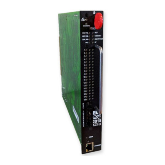
2018KCL Series
18 Channel RMS Signal Monitor with Datakey
Operations Manual
THIS MANUAL CONTAINS TECHNICAL INFORMATION FOR
THE 2018KCL and 2018KCLip, PCB Issue G.
Firmware Version 0156, 0456
REVISION: FEBRUARY 2016
pn 888-2018-001
- NOTE -
EDI ECCOM SOFTWARE MUST BE UPDATED TO VERSION 4.2 OR HIGHER.
EDI MONITORKEY SOFTWARE MUST BE UPDATED TO VERSION 2.4 OR HIGHER.
EDI SOFTWARE IS AVAILABLE AT WWW.EDITRAFFIC.COM
Advertisement
Table of Contents

Subscribe to Our Youtube Channel
Related Manuals for EDI 2018KCL Series


Summary of Contents for EDI 2018KCL Series
- Page 1 Firmware Version 0156, 0456 REVISION: FEBRUARY 2016 pn 888-2018-001 - NOTE - EDI ECCOM SOFTWARE MUST BE UPDATED TO VERSION 4.2 OR HIGHER. EDI MONITORKEY SOFTWARE MUST BE UPDATED TO VERSION 2.4 OR HIGHER. EDI SOFTWARE IS AVAILABLE AT WWW.EDITRAFFIC.COM...
- Page 2 THE 2018KCL SERIES SIGNAL MONITOR UNIT IS DESIGNED AND MANUFACTURED IN THE USA BY EBERLE DESIGN INC., PHOENIX, ARIZONA. INFORMATION CONTAINED HEREIN IS PROPRIETARY TECHNICAL INFORMATION OF EBERLE DESIGN INC. PUBLICATION, REPRODUCTION OR USE IN WHOLE OR PART IS NOT PERMITTED EXCEPT UNDER TERMS AGREED UPON IN WRITING.
-
Page 3: Table Of Contents
3.2 Status and Event Reporting ...................17 3.2.1 BI Tran Systems 233 Program Monitor Status..........17 3.2.2 EDI ECcom Monitor Report ................17 3.2.3 EDI ECcom Monitor Event Log Examples ............18 3.3 Signal Sequence Event Log ..................20 Section 4 INSTALLATION ....................22 4.1 Adapting Red Monitoring ..................22 4.1.1 Red Field Inputs ...................22... - Page 4 4.2.7 Clearance Enable Parameters ..............25 4.2.8 Yellow Disable Parameters ................25 4.2.9 Flashing Yellow Arrow (FYA / FYAc) Parameters .........25 Section 5 FRONT PANEL DESCRIPTION ...............26 5.1 Indicators ......................26 5.1.1 AC PWR Indicator ..................26 5.1.2 VDC Indicator ....................26 5.1.3 WDT Indicator ....................26 5.1.4 CONFLICT Indicator ..................26 5.1.5 RED FAIL Indicator ..................26 5.1.6 DUAL IND Indicator..................26...
-
Page 5: Section 1 Basic Functions
2018KCL(ip) SERIES SIGNAL MONITOR OPERATIONS MANUAL Section 1 BASIC FUNCTIONS 1.1 MODEL DESCRIPTION The model 2018KCL unit is an eighteen channel version of the 2010ECL model, and is compatible with the requirements of both the 170 Controller Unit and the 2070 Advanced Traffic Controller. -
Page 6: Conflict Monitoring
2018KCL(ip) SERIES SIGNAL MONITOR OPERATIONS MANUAL 1.2.1.1 MONITORKEY CONFIGURATION SET-UP WIZARD ® The Set-up Wizard in the MonitorKey program can be used to automatically generate all the enhanced monitor programming data for the 2018KCL in most cases without the need for understanding complex and confusing monitor terminology. -
Page 7: Section 2 Extended Features
2018KCL(ip) SERIES SIGNAL MONITOR OPERATIONS MANUAL Section 2 EXTENDED FEATURES The following extended features are provided on the Signal Monitor to provide additional fault monitoring functions, to increase the reliability of the monitor operation, and enhance the diagnostic capabilities offered to the service technician. 2.1 HARDWARE FEATURES The 2018KCL is a dual microprocessor based unit. -
Page 8: Red Interface Cable Fault
2018KCL(ip) SERIES SIGNAL MONITOR OPERATIONS MANUAL 2.2.1 RED INTERFACE CABLE FAULT When inserted into the output file without the Red Interface cable assembly, the 2018KCL will operate as a standard 210 signal monitor, that is, the Red Fail, Dual Indication, and Clearance monitoring functions will be disabled. -
Page 9: Ac Line Brown-Out Detection
2018KCL(ip) SERIES SIGNAL MONITOR OPERATIONS MANUAL illuminating the CLEARANCE indicator, transferring the Output relay contacts to the fault position and enabling the Stop-Time output to the controller. Minimum Yellow Plus Red Clearance monitoring is enabled on a per channel basis using the Minimum Yellow Plus Red Clearance Enable programming in the Datakey (see section 4.2.7.2) and requires the controller cabinet assembly to be adapted for Red Signal Monitoring. -
Page 10: Recurrent Pulse Detection
Pulse Disable option in the Datakey, see section 4.2.3.9. 2.8 EXIT FLASH When the 2018KCL series exits the flash state (Output relay de-energized) as a result of a Reset command or AC Line brownout restore, the Stop Time output will go to the inactive state 250 _ + 50 ms before the Output relay transfers to the energized state. -
Page 11: Key (Datakey Absent) Indication
2018KCL(ip) SERIES SIGNAL MONITOR OPERATIONS MANUAL Stop-Time output will remain in the fault mode and the correct fault and channel indicators will be displayed. The 2018KCL use a lifetime lithium battery to maintain the time of day clock. Should this battery fail, only current time and date functions will be lost. -
Page 12: Led Test
2018KCL(ip) SERIES SIGNAL MONITOR OPERATIONS MANUAL than 500 milliseconds, the monitor will resume monitoring functions and the Reset command will then provide input to the Diagnostic Display mode (see Section 2.18). 2.14 LED TEST The monitor will illuminate all front panel indicators for 500 milliseconds when a Reset command is issued by the front panel Reset button or External Reset Input. -
Page 13: Flashing Yellow Arrow (Fya) Overview
2018KCL(ip) SERIES SIGNAL MONITOR OPERATIONS MANUAL the RP DETECT indicator will then flash simultaneously at a 4 Hz rate with the input(s) that had Recurrent Pulse status for an additional 2 seconds following the fault channel display. The two previous faults may be also be displayed individually. This status is not reset by an AC Line power interruption. -
Page 14: Fya Mode
2018KCL(ip) SERIES SIGNAL MONITOR OPERATIONS MANUAL 2.19.1 FYA MODE In the FYA mode (see Table 2-1), the cabinet must be wired such that for each FYA approach, the solid Green protected Arrow is driven by a load switch monitored on channels 1, 3, 5, and 7. - Page 15 2018KCL(ip) SERIES SIGNAL MONITOR OPERATIONS MANUAL Signal Monitor will remain in the fault mode until the unit is reset by the RESET button or the EXTERNAL RESET input. 2.19.1.1.3 RED FAIL A Red Fail fault will occur if the solid Red Arrow AND solid Yellow Arrow AND flashing Yellow Arrow AND solid Green Arrow all remain inactive for the Red Fail fault response time.
-
Page 16: Fyac (Compact) Mode
2018KCL(ip) SERIES SIGNAL MONITOR OPERATIONS MANUAL - WARNING - IF THE PERMISSIVE FLASHING YELLOW ARROW AND PROTECTED GREEN ARROW CHANNEL ASSIGNMENTS ARE SWAPPED SUCH THAT THE FYA INPUT IS MONITORED ON CHANNELS 1,3,5, AND 7: 1) The Flashrate Fault function monitors the enabled flashing Yellow Arrow input of channels 9,10,11, and 12. - Page 17 2018KCL(ip) SERIES SIGNAL MONITOR OPERATIONS MANUAL Yellow Arrow, and flashing Yellow Arrow is monitored on channels 1, 3, 5, and 7 respectively. The Signal Monitor associates channel 1 with 9, channel 3 with 10, channel 5 with 11, and channel 7 with 12, when FYAc monitoring is enabled for that respective approach.
- Page 18 2018KCL(ip) SERIES SIGNAL MONITOR OPERATIONS MANUAL 2.19.2.1.2 FLASH RATE DETECTION When the FLASHRATE FAULT option is not disabled (see Section 4.2.9.1), the Signal Monitor will monitor a flashing yellow arrow output for a lack of flashing operation. If any of the enabled flashing yellow arrow signals on channels 1,3,5,7 remain active for more than the FYA Flash Rate Fault time (Section 8.1.4), the Signal Monitor will enter the fault mode, transfer the OUTPUT relay contacts to the Fault position, and display status.
- Page 19 2018KCL(ip) SERIES SIGNAL MONITOR OPERATIONS MANUAL Monitor Physical Input Monitor Logical Channel Associated FYA Channel Ch 10 Green Ch 11 Green Ch 5 Ch 10 Yellow Ch 12 Green Ch 7 The associated solid Red Arrow, solid Yellow Arrow, and flashing Yellow Arrow phases must be driven by a load switch monitored on channels 1, 3, 5, and 7 respectively.
- Page 20 2018KCL(ip) SERIES SIGNAL MONITOR OPERATIONS MANUAL NOTE: This example is for illustrative purposes ONLY. Permissive Programming for an application depends on actual intersection geometry, cabinet wiring, and Controller programming. Eberle Design Inc. Page 16...
-
Page 21: Section 3 Event Logging Features
Software manual should be consulted for details of operation. 3.2.2 EDI ECCOM MONITOR REPORT The EDI ECcom software package (Version 3.6.4 or greater is required) interfaces a Computer to the model 2018KCL. The ECcom program will display the Status (S), Previous Fault (PF) event log, AC Line (AC) event log, Manual Reset (MR) event log, Configuration (CF) event log, and Fault Trace log. -
Page 22: Edi Eccom Monitor Event Log Examples
1) Previous Fault (PF) Event Log >> Previous Fail Event Log >> Monitor ID #73 >> EDI Model 2018KCL, Firmware Type 01, Firmware V5.0, Comm V3.6 >> RMS-Engine Firmware Type 01, RMS-Engine Firmware V2.3 >> ECcom Version 3.6.4 >> Downloaded at 10:23:35 AM Friday, September 22, 2006 >>... - Page 23 2) AC Line (AC) Event Log >> AC Line Event Log >> Monitor ID #73 >> EDI Model 2018KCL, Firmware Type 01, Firmware V5.0, Comm V3.6 >> RMS-Engine Firmware Type 01, RMS-Engine Firmware V2.3 >> ECcom Version 3.6.4 >> Downloaded at 10:21:27 AM Friday, September 22, 2006 >>...
-
Page 24: Signal Sequence Event Log
2018KCL(ip) SERIES SIGNAL MONITOR OPERATIONS MANUAL Green-Yellow Dual Enable: 9 10 11 12 13 14 15 16 17 18 Yellow-Red Dual Enable: 9 10 11 12 13 14 15 16 17 18 Green-Red Dual Enable: 9 10 11 12 13 14 15 16 17 18 Clearance Enables (X=Enable): Minimum Yellow Clearance Enable: 9 10 11 12 13 14 15 16 17 18... - Page 25 2018KCL(ip) SERIES SIGNAL MONITOR OPERATIONS MANUAL Eberle Design Inc. Page 21...
-
Page 26: Section 4 Installation
2018KCL(ip) SERIES SIGNAL MONITOR OPERATIONS MANUAL Section 4 INSTALLATION The 2018KCL is a plug-in module for the Type 170/179 output file. When inserted into the output file without the Red Interface cable assembly, it will operate as a standard 210 signal monitor. -
Page 27: Datakey Parameters
4.2.3.2 ETHERNET COMM PORT SETTINGS (2018KCLIP) The Ethernet port must be configured with specific network parameters such as an IP address. The network port parameters are set or changed using the EDI ECcom Signal Monitor Communications software. See the "EDI ECcom Software Operations Manual"... - Page 28 2018KCL(ip) SERIES SIGNAL MONITOR OPERATIONS MANUAL 4.2.3.4 MONITOR ID NUMBER A monitor ID number can be set in the range of 0 to 99999999. This ID number is used when retrieving event logs from the 2018KCL. 4.2.3.5 MONITOR ID NAME A forty character monitor ID name can be set.
-
Page 29: Permissive Channel Pair Parameters
2018KCL(ip) SERIES SIGNAL MONITOR OPERATIONS MANUAL 4.2.4 PERMISSIVE CHANNEL PAIR PARAMETERS These parameters define the conflict matrix. For each primary channel from 1 to 17, the check boxes select which channels are permitted to be active concurrently with the primary channel (compatible). -
Page 30: Section 5 Front Panel Description
2018KCL(ip) SERIES SIGNAL MONITOR OPERATIONS MANUAL Section 5 FRONT PANEL DESCRIPTION 5.1 INDICATORS 5.1.1 AC PWR INDICATOR The AC PWR indicator will illuminate when the AC Line voltage level is above the brown- out "restore" level. The indicator will flash at a rate of 2Hz when the AC Line voltage is below the "drop-out"... -
Page 31: Diagnostic Indicator
2018KCL(ip) SERIES SIGNAL MONITOR OPERATIONS MANUAL 5.1.9 DIAGNOSTIC INDICATOR The DIAGNOSTIC indicator will illuminate when an internal hardware or firmware test function has failed. This indicator is intended to inform the service technician of a monitor hardware or firmware failure. Due to the nature of these hardware or firmware failures, other fault indicators that may be concurrently illuminated may not be valid for trouble shooting purposes. -
Page 32: Section 6 Circuit Operation
2018KCL SERIES SIGNAL MONITOR OPERATIONS MANUAL Section 6 CIRCUIT OPERATION 6.1 INTRODUCTION The Signal Monitor uses a dual microprocessor architecture consisting of an 68HC11D0 main microprocessor unit (MPU) and a Microchip PIC17F242 based RMS-Engine. The RMS-Engine is a dedicated single-chip high speed microcontroller used to sample the AC field inputs and calculate the true Root Mean Squared (RMS) voltage. -
Page 33: Real Time Clock
2018KCL SERIES SIGNAL MONITOR OPERATIONS MANUAL 6.7 REAL TIME CLOCK The DS1305 Real Time Clock (U29) provides the timekeeping function. It transfers data to the main MPU using the serial SPI interface. During normal operation the RTC is synchronized to the 60 Hz AC Line for long term accuracy. The lifetime lithium battery (BATT1) provides power to the RTC when AC Line voltage is not present. -
Page 34: Section 7 Trouble Shooting
2018KCL SERIES SIGNAL MONITOR OPERATIONS MANUAL Section 7 TROUBLE SHOOTING SYMPTOMS: Will not power on CAUSES: Blown fuse Internal power supply is low No AC input to the monitor SOLUTIONS: Remove the fuse and verify with an Ohm meter. Replace if necessary with a fuse with the same current rating. - Page 35 2018KCL SERIES SIGNAL MONITOR OPERATIONS MANUAL CAUSES: Permissive Channel pair programming in the Datakey is not correct. SOLUTIONS: Review the programming with the cabinet channel assignment for correctness and consistency. Eberle Design Inc. Page 31...
-
Page 36: Section 8 Specifications
2018KCL SERIES SIGNAL MONITOR OPERATIONS MANUAL Section 8 SPECIFICATIONS 8.1 ELECTRICAL 8.1.1 POWER REQUIREMENTS Operating Line Voltage ................. 75 to 135 Vrms Operating Line Frequency ..................60 _ + 3Hz Power Consumption ..................5W (nominal) 8.1.2 AC VOLTAGE MONITORS Green Signal Inputs (no detect) .......... -
Page 37: Timing Functions
2018KCL SERIES SIGNAL MONITOR OPERATIONS MANUAL 8.1.4 TIMING FUNCTIONS Conflict (no fault)........less than 200 milliseconds (fault) ........greater than 500 milliseconds (typical) ............350 milliseconds VDC Failed (no fault)........less than 200 milliseconds (fault) ........greater than 500 milliseconds (typical) ............ -
Page 38: Section 9 Wiring Assignments
2018KCL SERIES SIGNAL MONITOR OPERATIONS MANUAL Section 9 WIRING ASSIGNMENTS 9.1 MONITOR UNIT CONNECTOR (P6) - WARNING - PIN 27 OF THE MAIN CONNECTOR (P6) PROVIDES THE CLOSED CONTACT OF THE OUTPUT RELAY WHEN THE MONITOR IS IN THE NO-FAULT STATE. WHEN THE MONITOR IS IN THE NO-FAULT STATE AND THE AUTO/FLASH SWITCH IS IN THE FLASH POSITION, AC LINE VOLTAGE MAY BE PRESENT ON PIN 27. -
Page 39: Program Card Connector
2018KCL SERIES SIGNAL MONITOR OPERATIONS MANUAL OUTPUT SW, SIDE #1 closes in the fault mode. OUTPUT SW, SIDE #3 opens in the fault mode. 9.2 PROGRAM CARD CONNECTOR Pin # Function Pin # Function CHANNEL 2 GREEN CHANNEL 1 GREEN... -
Page 40: Eia-232 Connector (J1)
2018KCL SERIES SIGNAL MONITOR OPERATIONS MANUAL **Note: Pin #4 may be used to connect the monitor chassis to the cabinet CHASSIS GROUND. To complete this connection, a soldered wire jumper must be placed in location E1. Monitor CHASSIS GROUND is also connected through the edge connector P6. The... -
Page 41: Ethernet Lan Port
Monitor Communications software. See the "EDI ECcom Software Operations Manual" for details on the SETUP / COMM PORT / SETTINGS / Search function. The network port parameters can also be configured in the Datakey. See the EDI ECcom Operation Manual (pn 888-1000-001) and MonitorKey Operations Manual (pn 888- 1212-001) for details.
Need help?
Do you have a question about the 2018KCL Series and is the answer not in the manual?
Questions and answers