
Subscribe to Our Youtube Channel
Related Manuals for EDI LMD222


Summary of Contents for EDI LMD222
- Page 1 LMD222 and LMD224 Inductive Loop Monitor Operations Manual THIS MANUAL CONTAINS TECHNICAL INFORMATION FOR THE LMD222, LMD224 and LMD222-R SERIES INDUCTIVE LOOP MONITOR. REVISION: AUGUST 2015 pn 888-0222-003...
- Page 2 THE LMD222 and LMD224 SERIES IS DESIGNED AND MANUFACTURED IN THE USA BY EBERLE DESIGN INC. PHOENIX, ARIZONA AN ISO 9001:2008 REGISTERED COMPANY INFORMATION CONTAINED HEREIN IS PROPRIETARY TECHNICAL INFORMATION OF EBERLE DESIGN INC. PUBLICATION, REPRODUCTION OR USE IN WHOLE OR PART IS NOT PERMITTED EXCEPT UNDER TERMS AGREED UPON IN WRITING.
-
Page 3: Table Of Contents
4.4.4 Lead-in Length ....................9 4.5 Loop Input (Lightning Protection) ................9 4.6 Response Timing ....................10 4.6.1 LMD222 Series Response Timing ..............10 4.6.2 LMD224 Series Response Timing ..............10 4.7 LMD222 Connector Pin Assignments ..............10 4.8 LMD224 Connector Pin Assignments ..............10... -
Page 4: Section 1 General
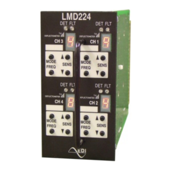
Operations Manual Section 1 GENERAL 1.1 DESCRIPTION The LMD222 two channel and LMD224 four channel rack-mounted inductive Loop Monitor ® with DEFLECTOMETER Series is built on the international card format with double-sided 44 pin edge connectors for connection of power, loop inputs and call outputs. The ®... - Page 5 LMD222 and LMD224 Series Operations Manual The unit will detect inductance changes as small as 0.010% ∆L/L. Each channel is sequentially energized and sampled so as to negate the possibility of crosstalk between loops connected to different channels of the same detector.
-
Page 6: Section 2 Installation And Adjustments
LMD222 and LMD224 Series Operations Manual Section 2 Installation and Adjustments 2.1 SET THE SENSITIVITY LEVEL ® The DEFLECTOMETER (front panel 7-segment LED display) aids in setting the detector to the most optimum sensitivity level to ensure the detection of all vehicles, including motorcycles and high bed vehicles. -
Page 7: Adjusting Sensitivity Directly
Note that each change of the Sensitivity Level while in this “direct adjust” mode causes the LMD Series to retune. Caltrans sensitivity levels 1, 2, and 3 are equivalent to the LMD222 and LMD624 levels of 3, 4, and 5 respectively. -
Page 8: Minimum Presence Time
LMD222 and LMD224 Series Operations Manual 2.2.4 MINIMUM PRESENCE TIME When the diode (1N4148WS) labeled OPT4 is installed, the LMD Series will limit the minimum presence time to 100 milliseconds. 2.2.5 PULSE MODE (P) The Pulse mode will provide a 125 ms ± 25ms width output pulse for each vehicle entering the loop. -
Page 9: Retune Or Reset A Channel
LMD222 and LMD224 Series Operations Manual 2.4.2 RETUNE OR RESET A CHANNEL Press the MODE and FREQ buttons simultaneously to reset the channel. This will clear any previous loop fault indication and cause the channel to retune. 2.4.3 FACTORY DEFAULT SETTINGS Press the Channel 1 MODE and FREQ buttons simultaneously while first applying power to the unit to reset all channels to the factory default settings. -
Page 10: Section 3 Loop Installation
LMD222 and LMD224 Series Operations Manual Section 3 Loop Installation The typical sensing height is 2/3 of the shortest leg of a loop (in feet). Therefore a 4’ x 8’ loop typically has a detection height of 2.6’. The inductance of a conventional four-sided loop can be estimated using the formula:... - Page 11 LMD222 and LMD224 Series Operations Manual circumference to prevent the loop wire from rising up while the sealant is poured and curing. Many different types of loop sealant are now available. Single part types are the easiest to apply since no mixing is required, but they also tend to be more expensive in terms of linear feet of saw slot filled.
-
Page 12: Section 4 Specifications
Operations Manual Section 4 Specifications 4.1 MECHANICAL Height ......................4.50 inches LMD222 Width ................... 1.14 inches LMD224 Width ................... 2.34 inches Depth (excluding handle) ................6.875 inches 4.2 ENVIRONMENTAL Storage Temperature Range ..............-45 to +85 Operating Temperature Range ..............-34 to +74 Humidity Range (non-condensing) ............. -
Page 13: Response Timing
LMD222 and LMD224 Series Operations Manual 4.6 RESPONSE TIMING This table assumes that all channels are set to the same Sensitivity Level. 4.6.1 LMD222 SERIES RESPONSE TIMING Sensitivity Level Response Sensitivity Level Response 40 +/- 15ms 3 +/- 1ms 19 +/- 7ms... - Page 14 LMD222 and LMD224 Series Operations Manual Function Function External Reset Reserved Channel 1 Loop Input Channel 1 Redundant Loop Input Channel 1 Loop Input Channel 1 Redundant Loop Input Channel 1 Output (+) Reserved Channel 1 Output (-) Reserved Channel 2 Loop Input...
Need help?
Do you have a question about the LMD222 and is the answer not in the manual?
Questions and answers