
Subscribe to Our Youtube Channel
Related Manuals for EDI NSM-3E


Summary of Contents for EDI NSM-3E
- Page 1 NSM-3E NEMA TS-1 Enhanced Signal Monitor Operations Manual THIS MANUAL CONTAINS TECHNICAL INFORMATION FOR THE NSM-3E SERIES SIGNAL MONITOR UNIT. REVISION: JULY 2017 pn 888-0003-002...
- Page 2 THE NSM-3E SERIES MONITORS ARE DESIGNED AND MANUFACTURED IN THE USA BY EBERLE DESIGN INC., PHOENIX, ARIZONA, AN ISO 9001:2008 REGISTERED COMPANY INFORMATION CONTAINED HEREIN IS PROPRIETARY TECHNICAL INFORMATION OF EBERLE DESIGN INC. PUBLICATION, REPRODUCTION OR USE IN WHOLE OR PART IS NOT PERMITTED EXCEPT UNDER TERMS AGREED UPON IN WRITING.
-
Page 3: Table Of Contents
Table of Contents Section 1 Standard Functions ..................1 1.1 Introduction ......................1 1.2 Conflict Monitoring....................1 1.3 Red Failure Monitoring ................... 1 1.3.1 Walk Disable (Red Monitoring) ..............2 1.4 Voltage Monitoring ....................2 1.4.1 Voltage Monitor Fault Latch ................2 1.4.2 CVM Fault Latch ................... - Page 4 5.1.4 Logic Inputs ....................10 5.2 Timing Functions ....................10 5.3 Mechanical ......................11 5.4 Environmental .......................11 Section 6 Wiring Assignments ..................12 6.1 NSM-3E Monitor Unit Connector A ................12...
-
Page 5: Section 1 Standard Functions
The NSM-3E Signal Monitor will then display the appropriate fault status along with the proceed indications active at the time of the fault. The NSM-3E Signal Monitor will remain in this fault mode until a reset command is issued via the front panel RESET button or External Test Reset Input. -
Page 6: Walk Disable (Red Monitoring)
When enabled, the Red Monitoring function will not monitor the Walk field outputs. Absence of signals on the Green, Yellow, and Red field outputs of a channel will place the NSM-3E Signal Monitor into the fault mode causing the Output relay contacts to transfer. This function is enabled by the front panel option switch labeled "WALK DISABLE". -
Page 7: Section 2 Extended Features
This monitoring function detects simultaneous indications of active Green, Yellow, Walk, and Red field signal outputs on the same channel on the NSM-3E Signal Monitor. A Dual Indication fault places the NSM-3E Signal Monitor into the fault mode causing the Output relay contacts to transfer. -
Page 8: Walk Disable (Dual Indication Monitoring)
Recurrent Pulse detection algorithm will combine these pulses into one event and trigger a Conflict fault once the longer recurrent timing threshold is exceeded. When triggered by a recurrent fault condition, the NSM-3E Signal Monitor will enter the fault mode causing the Output relay contacts to transfer and illuminate the appropriate CONFLICT, DUAL INDICATION, or RED FAIL indicator along with the RP STATUS indicator. -
Page 9: Ledguard ® Led Field Signal Sensing
This function prevents the cabinet controller from being operated with the monitor disabled due to a faulty Reset button or External Reset input. The NSM-3E Signal Monitor monitors the state of the front panel Reset button and the External Reset input. When a Reset... -
Page 10: Section 3 Installation
Installation 3.1 HARNESSING CONNECTORS All field terminations are brought into the NSM-3E Signal Monitor by means of MIL-C-26482 connectors. The outside harnesses are not interchangeable between any of the 6, 12, or 18 channel monitors as defined by NEMA Traffic Control Systems Specification (TS-1, part 6), i.e., a 6 channel harness assembly will not mate with a 3 channel signal monitor. -
Page 11: Walk Disable
NSM-3E Signal Monitor Unit Operations Manual 3.4.3 WALK DISABLE Set this switch to the ON position to remove the Walk inputs from Red Fail and Dual Indication monitoring. See Sections 1.3.1 and 2.2.2 3.4.4 CVM LATCH Set this switch to the ON position to change a CVM fault to the latched state. See Section 1.4.2. -
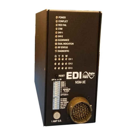
Page 12: Section 4 Front Panel Description
NSM-3E Signal Monitor Unit Operations Manual Section 4 Front Panel Description 4.1 STATUS DISPLAY 4.1.1 POWER INDICATOR The POWER indicator will flash at a rate of 2Hz when the AC+ line voltage goes below the drop-out level. It will illuminate steadily when the AC+ line voltage returns above the brown- out restore level. -
Page 13: Clearance Indicator
4.2 NO FAULT CHANNEL DISPLAY When the NSM-3E is not in the fault state, the unit will continuously display the active Green, Yellow, Walk and Red field status simultaneously on a four color LED full intersection display. -
Page 14: Section 5 Specifications
NSM-3E Signal Monitor Unit Operations Manual Section 5 Specifications 5.1 ELECTRICAL 5.1.1 POWER REQUIREMENTS Operating Line Voltage ................75 to 135 VAC RMS Operating Line Frequency ..................60 +_3Hz Power Consumption ..................5W (nominal) 5.1.2 AC VOLTAGE MONITORS (POSITIVE OR NEGATIVE HALF WAVE INPUT) Green Signal Inputs No Detect .......... -
Page 15: Mechanical
NSM-3E Signal Monitor Unit Operations Manual Red Fail No Fault ........less than 700 milliseconds Fault ........greater than 1000 milliseconds Typical ............850 milliseconds Controller Voltage Monitor, +24V Monitors No Fault ........less than 125 milliseconds Fault ......... greater than 175 milliseconds Typical ............ -
Page 16: Section 6 Wiring Assignments
NSM-3E Signal Monitor Unit Operations Manual Section 6 Wiring Assignments 6.1 NSM-3E MONITOR UNIT CONNECTOR A The NSM-3E Connector mates with a “MS 3116 20-41S” plug. TAG# PIN# Function AC+ I AC+ II OUTPUT RELAY 1 COMMON OUTPUT RELAY 1 OPEN...
Need help?
Do you have a question about the NSM-3E and is the answer not in the manual?
Questions and answers